Understanding the Need for Wiring Shielding
In industrial environments, photoelectric sensors are often exposed to electromagnetic interference (EMI) from motors, drives, and high-voltage cables. Unshielded wiring can lead to false triggering, signal loss, or erratic sensor behavior. Shielding is essential to maintain signal integrity, especially for long cable runs or in areas with high electrical noise. For reliable performance, always use shielded cables with a continuous metallic braid or foil wrap around the signal conductors. The shield acts as a Faraday cage, diverting external noise to ground and protecting the sensor’s output.
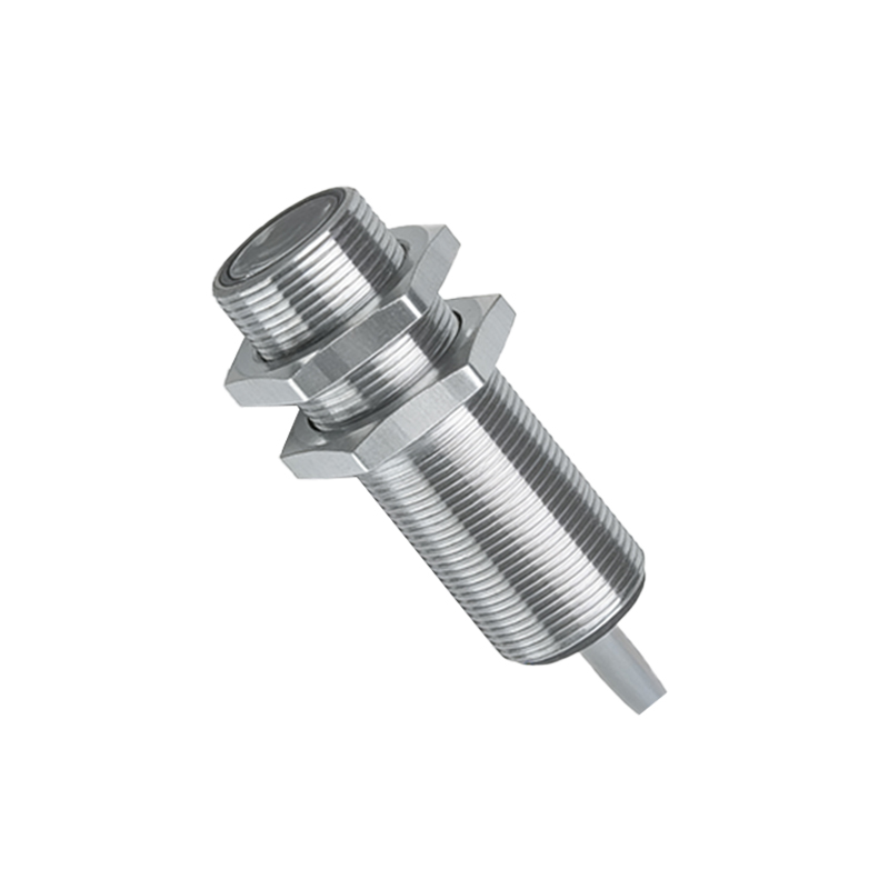
Selecting the Right Shielded Cable
Choose cables with a minimum of 80% braid coverage for critical applications. For photoelectric sensors operating in wet or oily conditions, opt for cables with an additional foil shield and a durable outer jacket, such as PVC or polyurethane. Ensure the cable’s conductor size (e.g., 22 AWG to 18 AWG) matches the sensor’s current requirements. Avoid using unshielded or flat ribbon cables, as they offer poor noise immunity. For sensors with M8 or M12 connectors, pre-assembled shielded cordsets are recommended to simplify installation and maintain compliance with IP67 or IP69K ratings.
Proper Grounding Techniques for the Shield
The shield must be grounded at one end only to prevent ground loops. Typically, ground the shield at the controller or PLC side, not at the sensor. Connect the drain wire or shield braid to a clean earth ground point using a screw terminal or grounding block. Do not rely on the sensor housing for grounding unless specified by the manufacturer. For long cable runs exceeding 100 meters, consider using a grounded junction box in the middle to split the cable and maintain signal quality. Always verify continuity with a multimeter before powering the system.
Wiring Configuration for Minimizing Noise
Run shielded sensor cables separately from power cables, keeping at least 30 cm (12 inches) of distance. Cross high-voltage lines at a 90-degree angle to reduce inductive coupling. For differential outputs, such as push-pull complementary, use twisted-pair cables within the shield to cancel common-mode noise. In systems with multiple photoelectric sensors, avoid daisy-chaining the shields; instead, each sensor’s shield should be individually grounded. Label each cable clearly to simplify troubleshooting.
Testing and Verification After Shielding
After wiring, test the system under full load. Use an oscilloscope to check the sensor’s output waveform for any noise spikes or glitches. Alternatively, measure the voltage between the signal line and ground with a high-impedance meter; fluctuations below 10 mV are acceptable for most digital sensors. If noise persists, verify the shield ground connection and check for loose braid strands that might create short circuits. Document the shielding setup for future maintenance.