Introduction to Photoelectric Sensors in Motor Control
Photoelectric sensors are essential components in modern industrial automation, particularly for precise motor speed control. These sensors detect changes in light intensity to measure rotational speed, offering non-contact, high-speed, and reliable feedback for closed-loop systems. In conveyor belts, robotics, and CNC machinery, photoelectric sensors ensure efficient operation by converting optical signals into electrical pulses, which controllers use to adjust motor RPM in real time. This article explores the engineering principles, implementation challenges, and performance optimization of photoelectric sensor-based motor speed control.
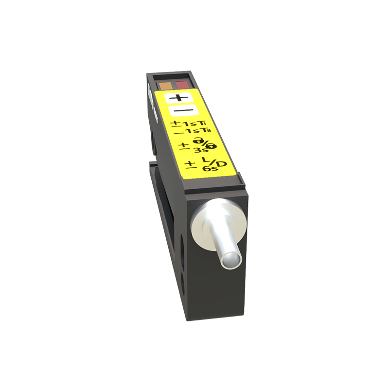
Operating Principle of Photoelectric Speed Sensors
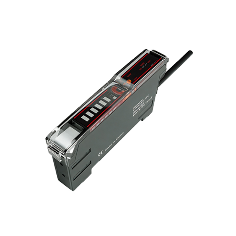
Photoelectric sensors for motor control typically use through-beam or reflective configurations. A rotating shaft is fitted with a slotted disk or reflective markers. As the shaft rotates, the sensor emits a light beam (usually infrared) that is interrupted or reflected by these markers. The photodetector generates a frequency-modulated pulse train proportional to rotational speed. For example, a disk with 60 slots produces 60 pulses per revolution, allowing a programmable logic controller (PLC) or microcontroller to calculate RPM using the formula: RPM = (Pulse Frequency × 60) / Number of Slots. This method enables accuracy within 0.1% of full scale, critical for applications like spindle control in lathes.
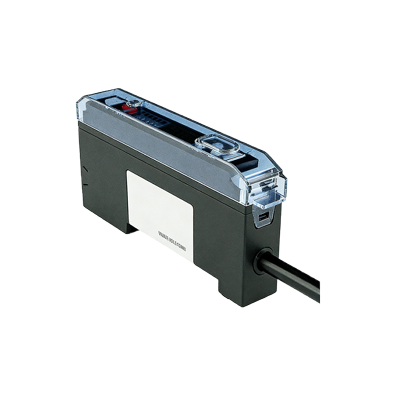
Key Selection Criteria for Industrial Photoelectric Sensors
Choosing the right sensor requires evaluating several parameters. Response time must be faster than the maximum expected pulse interval; for a motor running at 10,000 RPM with a 60-slot disk, pulses occur at 10 kHz, so sensor response time should be under 20 microseconds. Cable length and electrical noise immunity are vital in factory environments—shielded cables and sensors with IP67 ratings prevent interference from variable frequency drives. Output types include NPN, PNP, or push-pull, with push-pull preferred for compatibility with diverse PLC inputs. Additionally, ambient light filters and dust-resistant lenses extend reliability in harsh conditions.
Integration with Motor Drive Systems
Integrating photoelectric sensors with variable frequency drives (VFDs) requires careful wiring and programming. The sensor output connects to a high-speed digital input on the VFD or a dedicated pulse counter module. In a typical setup, the VFD uses this pulse signal as a feedback reference for PID control. For instance, in a conveyor system, the sensor measures actual belt speed, and the VFD adjusts motor frequency to maintain setpoint RPM. Engineers must configure acceleration and deceleration ramps to avoid overshoot—a common issue when sensor pulses are lost due to belt slip. Using a redundant sensor pair (e.g., one for speed, one for direction) enhances system safety.
Common Challenges and Troubleshooting Techniques
Despite reliability, photoelectric sensors face challenges in industrial settings. Contamination from oil mist or dust can scatter light, causing false pulses. Regular cleaning schedules and sensor enclosures with air purges mitigate this. Electrical noise from nearby high-power cables may induce spurious signals; installing ferrite cores and routing sensor cables away from power lines reduces interference. Another issue is misalignment of the slotted disk, which leads to pulse asymmetry. This is resolved by using photoelectric sensors with wide beam angles or self-aligning mounts. For high-vibration motors, sensors with spring-loaded brackets maintain consistent focus.
Performance Optimization and Calibration
Optimizing sensor performance involves calibrating the trigger level and hysteresis. For reflective sensors, adjusting the sensitivity pot ensures accurate detection of markers with varying reflectivity. Engineers should also verify pulse duty cycle—a 50% duty cycle indicates proper alignment. Advanced systems use adaptive filtering algorithms in the PLC to reject noise spikes shorter than 5 microseconds. Regular calibration using a tachometer reference ensures long-term accuracy. For example, a 5% deviation in pulse count at 1500 RPM warrants checking lens cleanliness or disk wear.
Future Trends in Photoelectric Sensor Technology
Emerging innovations include fiber-optic photoelectric sensors for hazardous environments and sensors with integrated signal processing that output direct RPM values via Modbus. LiDAR-based variants offer multi-axis speed detection for robotic arms. In Industry 4.0, photoelectric sensors with IIoT connectivity enable predictive maintenance by monitoring pulse pattern changes over time. These advances promise even higher resolution (up to 0.01 RPM) and reduced latency for next-generation motor control applications.