Introduction to Retroreflective Mounting Brackets
In industrial automation, photoelectric sensors are critical for non-contact detection, and retroreflective mounting brackets play a pivotal role in optimizing their performance. These brackets are specifically designed to hold retroreflective sensors, which emit a beam of light that is reflected back by a reflector. Unlike through-beam sensors, retroreflective systems require precise alignment. The bracket ensures the sensor and reflector are securely positioned, reducing vibration and misalignment. For engineers, selecting the right bracket involves considering materials like stainless steel or aluminum for durability, as well as environmental factors such as dust or moisture.
Key Design Features of Sensor Brackets
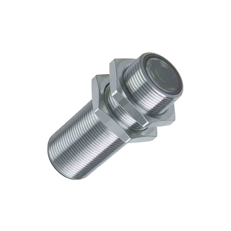
A well-designed retroreflective mounting bracket must offer adjustable angles and robust clamping mechanisms. Most brackets feature slotted holes or swivel joints to fine-tune the sensor’s orientation. For example, a common bracket type is the L-shaped bracket, which provides 90-degree mounting options for tight spaces. Another variant is the adjustable-angle bracket, allowing tilts of up to 45 degrees for complex installations. Material choices are crucial: zinc-plated steel resists corrosion, while anodized aluminum is lightweight and suitable for clean environments. Always verify the bracket’s load capacity against the sensor’s weight, especially for heavy-duty sensors used in conveyor systems.
Installation Best Practices for Optimal Performance
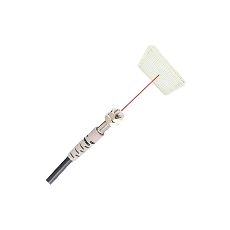
Proper installation of the retroreflective bracket ensures reliable sensor operation. First, mount the bracket on a stable surface, such as a machine frame or wall, using bolts or screws. Align the sensor head with the reflector, ensuring the light beam is parallel to the bracket’s axis. Use a laser alignment tool or a reflective tape indicator to check the path. Tighten all fasteners to the manufacturer’s torque specifications to prevent loosening from vibrations. In high-vibration environments, add lock washers or thread-locking compound. Test the sensor by moving an object across the beam; the output should trigger consistently without false signals.
Common Applications in Industrial Settings
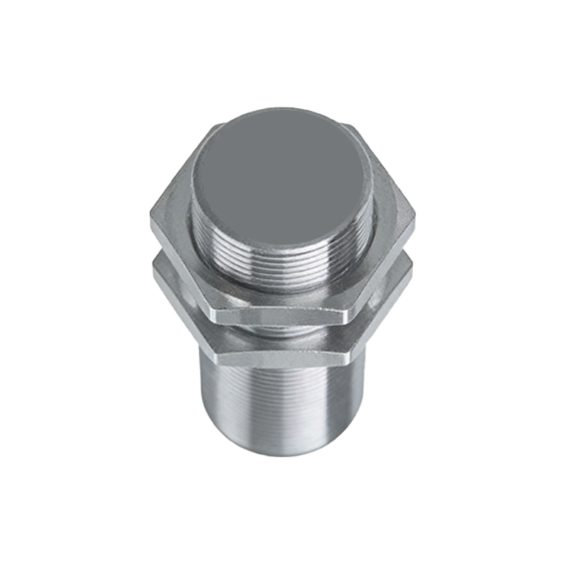
Retroreflective brackets are widely used in packaging lines, conveyor sorting systems, and automated storage. For instance, in a warehouse, brackets mount sensors to detect pallet positions on racks. In food processing, stainless steel brackets withstand washdown conditions. Automotive manufacturing employs brackets for part presence detection on assembly lines. The key advantage is that retroreflective sensors require only one bracket and a reflector, simplifying wiring compared to through-beam setups. This reduces installation costs and maintenance time.
Troubleshooting and Maintenance Tips
If a sensor fails, first inspect the bracket for physical damage or loosening. Check alignment: a skewed bracket can cause intermittent detection. Clean the bracket and reflector surfaces regularly, as dust or oil can scatter the light beam. Use a soft cloth and isopropyl alcohol for cleaning. Replace worn brackets if cracks or corrosion appear. For outdoor installations, consider UV-resistant brackets to prevent degradation. Document all bracket specifications for future maintenance.
Conclusion: Choosing the Right Bracket for Your System
Selecting a retroreflective mounting bracket depends on sensor type, environment, and installation angle. Prioritize brackets with adjustment flexibility and corrosion resistance. Review technical datasheets for mounting hole patterns and weight limits. By following these guidelines, electrical engineers can ensure reliable sensor performance in any automation project.