Introduction to Photoelectric Sensors
Photoelectric sensors are essential components in modern industrial automation, providing non-contact detection of objects, materials, and surfaces. Among the various types, the through-beam photoelectric sensor is widely used due to its high reliability and long sensing range. This article explains its schematic diagram and working principle from an electrical engineering perspective, focusing on key components and signal flow.
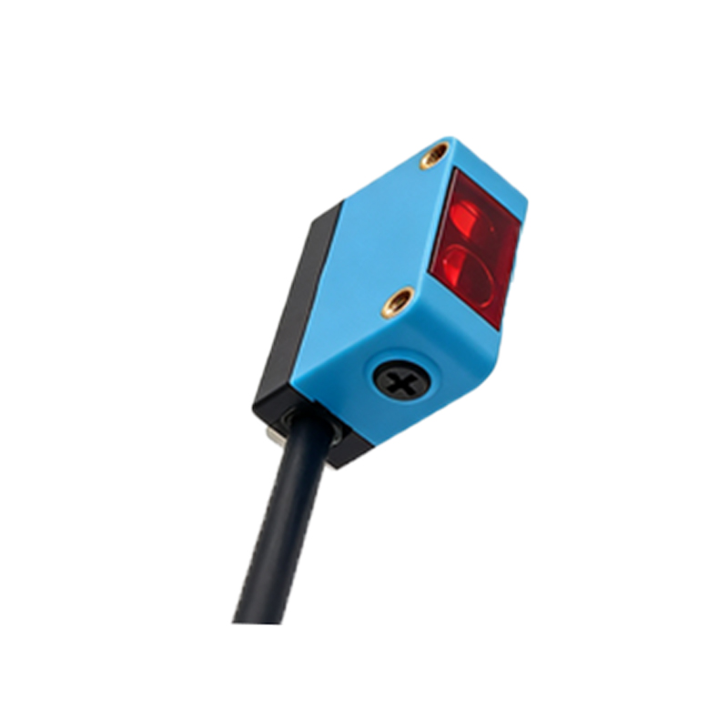
Basic Schematic Components
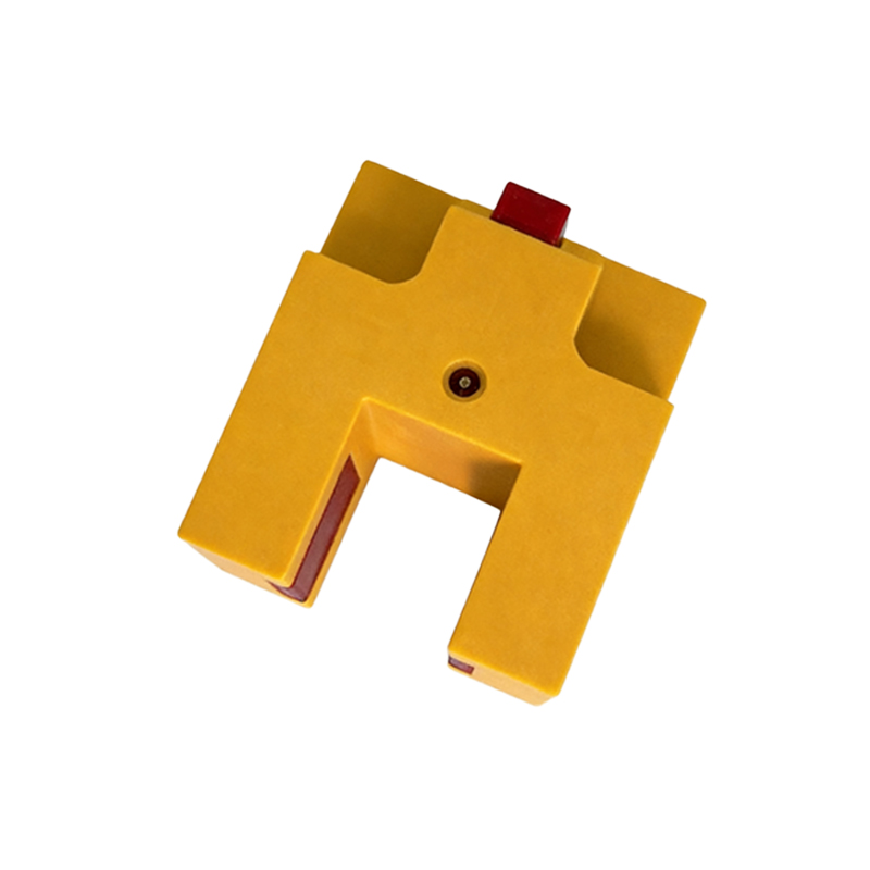
A typical through-beam photoelectric sensor consists of two separate units: an emitter and a receiver. The emitter contains a light source, usually an infrared LED (Light Emitting Diode), driven by a constant current source circuit to ensure stable optical output. The receiver is equipped with a photodiode or phototransistor, which converts incoming light signals into electrical current. The schematic shows the LED connected in series with a current-limiting resistor and a transistor driver, while the photodiode is reverse-biased and connected to a transimpedance amplifier.
Emitter Circuit Design and Operation
In the emitter circuit, the LED is powered by a regulated DC voltage, typically 5V to 24V. The transistor switch, controlled by a microcontroller or a timing circuit, modulates the LED on and off at high frequencies (e.g., 1 kHz to 10 kHz) to reduce interference from ambient light. The schematic includes a series resistor to limit current to the LED's safe operating range, usually 20 mA to 100 mA. A capacitor is often placed in parallel to filter power supply noise and ensure stable light pulses.
Receiver Circuit and Signal Processing
The receiver's photodiode operates in photovoltaic mode or photoconductive mode. In a typical schematic, the photodiode is reverse-biased with a voltage source, and its cathode connects to the input of a transimpedance amplifier (TIA). The TIA converts the small photocurrent (in the nanoamp to microamp range) into a proportional voltage. This voltage is then fed into a bandpass filter to select only the modulated frequency from the emitter, rejecting ambient light and noise. The filtered signal is compared to a threshold voltage using a comparator IC, which produces a clean digital output (high or low) indicating whether the light beam is blocked.
Alignment and Sensitivity Adjustment Circuits
The schematic often includes potentiometers for sensitivity adjustment. These are connected to the non-inverting input of the comparator to set the threshold level. Additionally, an alignment indicator LED is driven by the comparator output, providing visual feedback when the sensor is properly aligned. Engineers must ensure that the receiver's gain is adjustable to accommodate varying distances and environmental conditions.
Output Stage and Interface
The final stage of the schematic is the output driver, which typically uses an NPN or PNP transistor, or a push-pull configuration, to interface with PLCs or industrial controllers. A pull-up or pull-down resistor is included to set the default logic level. Protection diodes are added to safeguard against voltage spikes and reverse polarity. The output is labeled as "NO" (Normally Open) or "NC" (Normally Closed), depending on the application.
Practical Considerations for Engineers
When designing or troubleshooting photoelectric sensor circuits, consider power supply decoupling, grounding, and shielding. The schematic should minimize parasitic capacitance and inductance in the receiver path to maintain fast response times. Additionally, the emitter and receiver must be aligned precisely along the optical axis for maximum performance. For long-range applications, use collimating lenses or fiber optics, as shown in advanced schematic diagrams.
Conclusion
Understanding the schematic of a through-beam photoelectric sensor helps electrical engineers optimize system design, diagnose faults, and improve reliability. By analyzing each circuit block—from the emitter driver to the output interface—engineers can enhance sensor performance in harsh industrial environments.