Understanding Photoelectric Sensors
Photoelectric sensors are essential components in modern industrial automation, converting light signals into electrical outputs for object detection, positioning, and counting. These sensors operate by emitting a beam of light, typically infrared, visible red, or laser, and detecting changes in the received light intensity. As an electrical engineer, selecting the right sensor requires a deep understanding of its specific parameters to ensure reliable performance in harsh manufacturing environments. The following sections break down the critical parameters that define sensor capability and application suitability.
Detection Range and Sensing Distance
The detection range is the maximum distance at which a sensor can reliably detect an object. This parameter varies significantly by sensor type: through-beam sensors offer the longest range, often exceeding 30 meters, while retro-reflective models typically reach 10 meters, and diffuse sensors are limited to 2 meters or less. Engineers must consider environmental factors like dust, fog, or ambient light, which can reduce effective range. For example, in a conveyor system with high vibration, a sensor rated for 20 meters may only achieve 15 meters of reliable detection. Always refer to the datasheet’s “guaranteed detection distance” under worst-case conditions, not the ideal lab performance.
Response Time and Switching Frequency
Response time defines how quickly a sensor transitions from detection to output signal. Measured in milliseconds or microseconds, this parameter directly impacts high-speed applications such as bottle filling lines or packaging machinery. A fast sensor with a 0.5 ms response time can detect objects moving at 10 m/s with high precision. Switching frequency, often expressed in Hertz (Hz), indicates the maximum number of on-off cycles per second. For instance, a sensor with a 1 kHz switching frequency handles 1,000 detections per second. Engineers should match these values to the production line’s throughput, ensuring no missed detections due to sensor lag.
Light Source Type and Wavelength
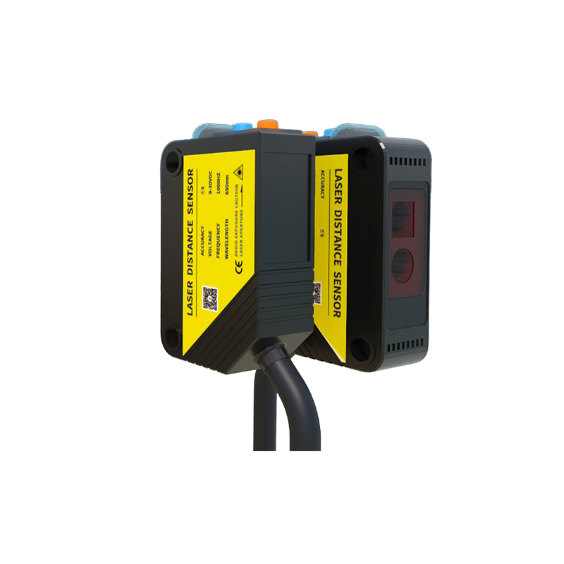
The light source determines the sensor’s performance against specific materials and conditions. Common sources include infrared (850-950 nm) for long-range detection, visible red (660 nm) for easy alignment, and laser (650-670 nm) for precision positioning. Infrared is ideal for transparent objects like glass or plastic, while visible red works well in dusty environments due to higher contrast. Laser sensors offer spot sizes as small as 0.1 mm, perfect for small target detection. Wavelength also affects immunity to ambient light: sensors with modulated light (pulsed) reject interference from sunlight or artificial lighting more effectively than continuous-wave types.
Output Type and Electrical Interface
Output configuration is critical for integrating sensors with PLCs, relays, or safety systems. Common outputs include NPN (sinking) and PNP (sourcing) for DC systems, and relay or solid-state AC outputs for high-current loads. Engineers must verify voltage ratings (e.g., 12-24 VDC or 24-240 VAC) and current capacity. For example, a PNP output with a 100 mA maximum is suited for direct PLC input, while a relay output can switch 2 A for motor starters. Additionally, consider digital outputs (IO-Link or AS-Interface) for advanced diagnostics and configuration, reducing downtime in complex networks.
Environmental Protection and Durability
Industrial environments demand sensors with robust enclosures and ratings. The ingress protection (IP) rating, such as IP67 or IP69K, defines resistance to dust and water. IP67 allows submersion in 1 meter of water for 30 minutes, while IP69K withstands high-pressure washdowns in food processing. Temperature range is another parameter: typical sensors operate from -25°C to 55°C, but extended-range models handle -40°C to 70°C for cold storage or oven applications. Vibration and shock resistance, often specified as 10-55 Hz at 1.5 mm amplitude, ensure reliability on moving machinery. Always validate these parameters against the specific operating conditions of your facility.
Conclusion: Selecting the Right Sensor
Mastering these parameters—detection range, response time, light source, output type, and environmental protection—enables engineers to choose photoelectric sensors that optimize system performance and longevity. A mismatch in any parameter can lead to false triggering, reduced efficiency, or premature failure. By analyzing the application’s speed, object characteristics, and ambient conditions, you can confidently specify sensors that deliver consistent, accurate results in demanding industrial settings. Always consult manufacturer guidelines for detailed specifications and consider field testing for critical installations.