Introduction to Optoelectronic Sensor Dry Contact
An optoelectronic sensor dry contact is a critical interface in industrial automation, where the sensor provides a voltage-free switching signal. Unlike analog or digital outputs, a dry contact acts as a simple on/off switch, isolating the sensor’s internal electronics from the control system. This design enhances safety and compatibility across various PLCs, relays, and controllers, making it a preferred choice in harsh environments.
How a Dry Contact Works in Optoelectronic Sensors
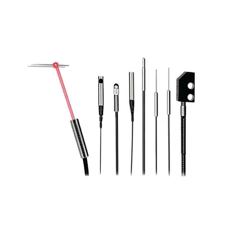
In optoelectronic sensors, the dry contact is typically realized via a relay or a transistor output that mimics a mechanical switch. When the sensor detects an object (e.g., via through-beam, retro-reflective, or diffuse mode), the internal circuit closes or opens the contact path. The term “dry” refers to the absence of a voltage source—the contact only completes or breaks an external circuit. This prevents electrical interference and simplifies integration with existing systems.
Key Advantages of Dry Contact Outputs
Dry contacts offer galvanic isolation, protecting sensitive control electronics from high voltages or surges. They are universally compatible with AC or DC loads, require no polarity consideration, and can switch both low-power signals and moderate currents. Additionally, they reduce false triggers caused by electrical noise, a common issue in factory automation settings.
Common Applications in Industrial Systems
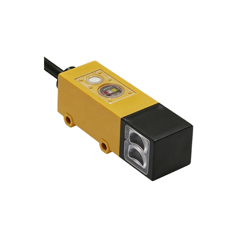
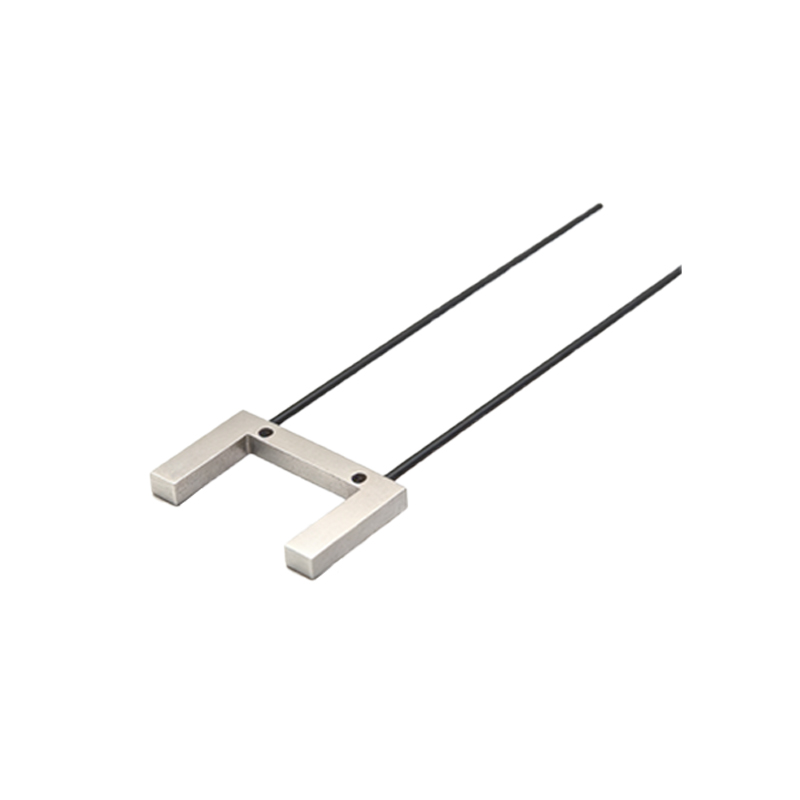
Typical applications include conveyor belt object detection, safety light curtains, door or gate position sensing, and level monitoring in tanks. For example, a photoelectric sensor with a dry contact output can directly activate a motor starter or alarm system without an intermediate interface relay. This simplifies wiring and reduces component count.
Wiring Guidelines and Best Practices
When wiring a dry contact sensor, always ensure the external power supply is turned off. Use shielded cables to avoid electromagnetic interference, especially in high-noise environments. Connect the common (COM) terminal to the load’s power source and the normally open (NO) or normally closed (NC) terminal to the load. For inductive loads like relays, add a flyback diode to suppress voltage spikes. Finally, verify the contact’s maximum current and voltage ratings to prevent overheating.
Troubleshooting Common Dry Contact Issues
If the sensor fails to trigger, check for loose connections, oxidized contacts, or misalignment of the optical path. Use a multimeter to measure continuity across the terminals when the sensor is activated. In high-vibration setups, consider using spring-clamp terminals instead of screw types to maintain stable contact. Also, ensure the load does not exceed the sensor’s switching capacity, which can cause contact welding.
Conclusion: Why Dry Contacts Remain Essential
Despite the rise of fieldbus and IO-Link technologies, dry contact outputs from optoelectronic sensors are still widely used for their simplicity, reliability, and isolation features. They provide a robust solution for legacy systems, safety circuits, and applications where minimal electrical noise is critical. Mastering their installation and troubleshooting ensures long-term system uptime.