2026-06-09
Tech Hub
By 创始人
Photoelectric Sensor Parallel Wiring Diagram: A Comprehensive Guide for Electrical Engineers
Introduction to Photoelectric Sensor Parallel Wiring
Photoelectric sensors, widely used in industrial automation, detect objects by emitting and receiving light beams. Parallel wiring is a common method to connect multiple sensors to a single controller, reducing installation complexity and cost. This guide provides a detailed wiring diagram and technical considerations for engineers.
Understanding Parallel Connection Fundamentals
In a parallel circuit, all sensors share the same power supply and signal lines. Each sensor operates independently, but their outputs are combined. For example, in a typical 3-wire NPN sensor, the brown wire connects to +V (e.g., 24V DC), the blue wire to 0V, and the black wire to the load. When wiring in parallel, all brown wires tie together, all blue wires tie together, and all black wires tie to the controller input. Ensure the total current draw does not exceed the power supply rating.
Wiring Diagram for Two Sensors in Parallel
Consider two photoelectric sensors (S1 and S2) connected to a PLC. Connect S1's brown wire to +24V, blue to 0V, and black to input I0.0. For S2, brown to same +24V, blue to same 0V, and black to same I0.0. This creates a logical OR function: if either sensor is triggered, the PLC input activates. Use a common ground to avoid ground loops. Include a 1A fuse in the power line for protection.
Key Electrical Characteristics and Limitations
Parallel wiring increases leakage current and noise. Each sensor's output transistor has a residual voltage drop (e.g., 2V at 100mA). In parallel, the total load current equals the sum of individual sensors, which may exceed the controller's input capacity. Use a pull-up resistor (e.g., 10kΩ) for PNP sensors to ensure stable logic levels. Also, cable length above 100 meters can cause voltage drop; use thicker gauge wires.
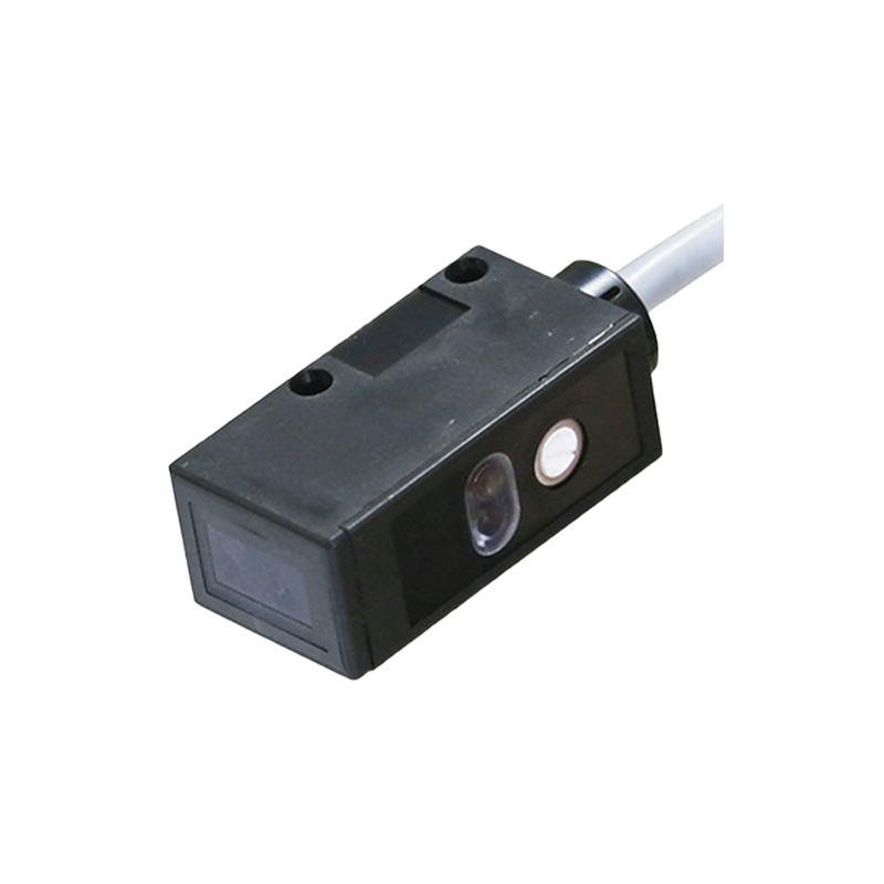
Application Example: Conveyor Line Monitoring
In a conveyor system, three sensors monitor product presence. Wire all sensor outputs to one PLC input. When any sensor detects a product, the conveyor control logic initiates a stop. To prevent false triggers, add a debounce time (e.g., 10ms) in the PLC program. Use shielded twisted-pair cables to reduce electromagnetic interference from motors.
Troubleshooting Common Issues in Parallel Wiring
Common problems include sensor crosstalk (interference between sensors) and voltage drop. If sensors activate incorrectly, check for reflected light from adjacent sensors. Isolate sensors with separate power supply branches or use sensors with different light frequencies. Measure voltage at each sensor's terminals; if below 20V, upgrade the power supply or reduce cable length.
Conclusion and Best Practices
For reliable parallel wiring, always calculate total current, use a dedicated power supply with 20% headroom, and follow color codes (IEC 61131-2). Label all wires clearly and test each sensor individually before combining. This method is cost-effective for simple on/off applications but not recommended for safety-critical systems without redundant designs.