Introduction to Photoelectric Distance Sensing
Photoelectric sensors have become a cornerstone in modern industrial automation, offering non-contact distance measurement with high precision and reliability. By emitting a beam of light—typically infrared or visible laser—and analyzing the reflected signal, these sensors determine the distance to a target object. Unlike traditional mechanical sensors, photoelectric devices eliminate wear and tear, making them ideal for harsh environments such as assembly lines, robotic arms, and material handling systems. Their ability to operate over long ranges with minimal interference ensures consistent performance in applications requiring real-time feedback.
Operating Principles of Photoelectric Sensors
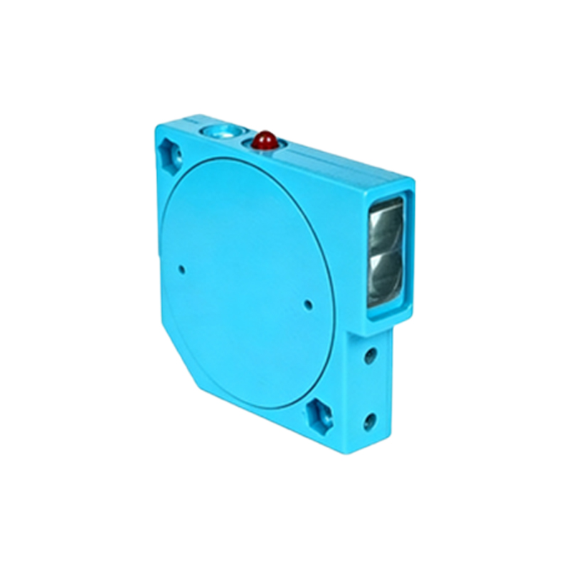
The core mechanism relies on the time-of-flight (ToF) method or triangulation. In ToF sensors, a pulsed light source measures the time taken for the signal to bounce back from the target, converting this into distance. Triangulation sensors, on the other hand, use a position-sensitive detector (PSD) to calculate the angle of the reflected beam, which varies with distance. Both methods offer distinct advantages: ToF excels in long-range detection up to tens of meters, while triangulation provides sub-millimeter accuracy for short-range applications. Engineers must consider ambient light conditions and target surface reflectivity when selecting the appropriate sensor type.
Key Selection Criteria for Industrial Use
When integrating photoelectric sensors for distance measurement, several factors demand attention. First, the detection range must match the application's physical constraints—for example, a conveyor belt monitoring system may require a sensor with a range of 10 to 50 meters. Second, response time is critical in high-speed sorting processes; sensors with microsecond-level switching frequencies are preferred. Third, environmental resilience is non-negotiable: sensors with IP67 ratings withstand dust and moisture in factory floors. Additionally, output types (analog voltage, current, or digital protocols like IO-Link) should align with existing control systems.
Calibration and Installation Best Practices
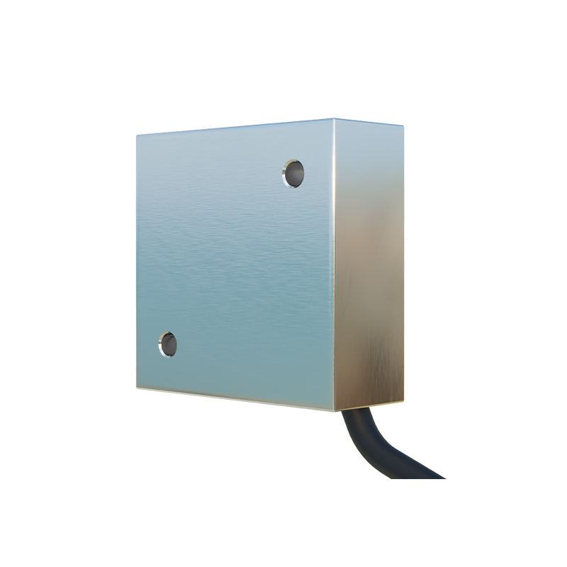
Proper calibration ensures accuracy and reduces measurement drift. Before installation, verify the sensor's alignment with the target surface using a laser alignment tool. For triangulation sensors, the baseline distance between the emitter and receiver must be fixed. In multi-sensor arrays, avoid crosstalk by staggering operating frequencies or using synchronized triggering. Mounting the sensor on vibration-dampened brackets minimizes noise from machinery. Regular recalibration every six months is recommended, especially in environments with temperature fluctuations or accumulating dust on optical windows.
Common Challenges and Solutions
Despite their robustness, photoelectric sensors face challenges such as interference from shiny or transparent targets. For transparent objects, retro-reflective sensors with polarization filters can mitigate false readings. Dark or matte surfaces may reduce signal strength; in such cases, selecting sensors with high sensitivity settings or supplementary lighting is effective. Electrical noise from nearby motors can corrupt signals, so shielded cables and ferrite cores are essential. Implementing a fail-safe logic in the PLC, such as checking for timeout errors, adds a layer of reliability.
Future Trends in Optical Distance Measurement
The evolution of photoelectric technology continues with the integration of artificial intelligence and edge computing. Smart sensors now feature self-learning algorithms to adapt to changing surface conditions without manual recalibration. The rise of Industry 4.0 demands sensors capable of seamless data integration with cloud-based analytics for predictive maintenance. Additionally, advancements in laser diode efficiency and cost reduction are expanding the use of 3D ToF cameras for complex spatial mapping in warehouse automation and autonomous guided vehicles.