Introduction to Photoelectric Sensors in Displacement Measurement
Photoelectric sensors are non-contact devices that detect the presence, distance, or position of an object using light. In displacement measurement, these sensors excel due to their high accuracy, fast response time, and adaptability to various surfaces. As an electrical engineer, understanding the working principles—through-beam, retro-reflective, and diffuse—is critical. For displacement tasks, diffuse sensors with analog output are most common, as they measure light intensity changes proportional to target distance. However, factors like target reflectivity, background interference, and ambient light must be calibrated to ensure reliable results.
Sensor Selection Criteria for Displacement Applications
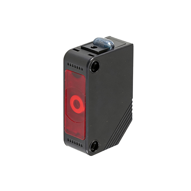
Choosing the right photoelectric sensor for displacement measurement requires evaluating key parameters. First, determine the measurement range: short-range (< 1 m) suits diffuse sensors, while long-range (> 10 m) favors through-beam types. Next, consider output type—analog voltage (0-10 V) or current (4-20 mA) for continuous displacement data, or digital for threshold detection. Resolution and linearity are vital; for precision tasks, opt for sensors with resolution< 0.1 mm and linearity error< 1%. Also, assess environmental factors like dust, moisture, and temperature, selecting sensors with IP67 rating and compensation algorithms for drift.
Installation and Alignment for Optimal Performance
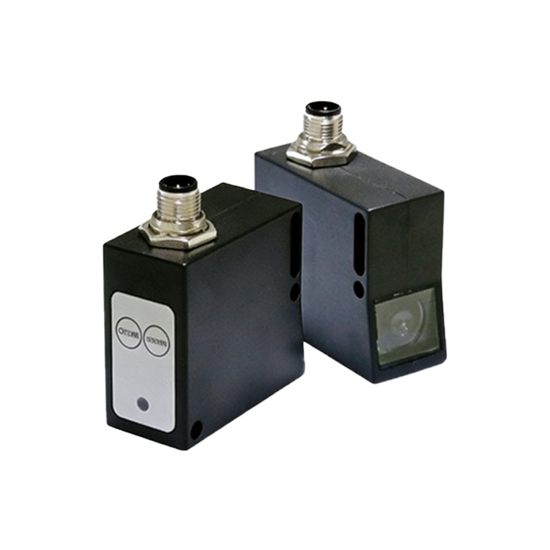
Proper mounting ensures accurate displacement readings. For diffuse sensors, align the emitter and receiver axis perpendicular to the target surface to minimize angular errors. Use a mounting bracket with fine adjustment screws to set the focal point within the sensor’s linear range. For through-beam setups, align the emitter and receiver directly, avoiding obstructions. Power the sensor with a stable DC supply (e.g., 24 V ± 10%) and shield cables from electromagnetic interference. Perform a static calibration by placing the target at known distances, recording output values, and creating a lookup table or linear regression curve.
Data Acquisition and Signal Processing
Connect the sensor output to an analog input module (e.g., PLC, DAQ, or microcontroller) with sufficient sampling rate (at least 10x the highest movement frequency). For example, if the target vibrates at 100 Hz, sample at 1 kHz. Apply a low-pass filter (e.g., moving average or Butterworth) to remove high-frequency noise from ambient light flicker or electrical noise. In software, convert raw voltage/current to displacement using the calibration curve. Implement hysteresis to avoid jitter near thresholds, and use a peak-hold function for dynamic measurements like maximum displacement during a stroke.
Practical Implementation Example: Linear Position Monitoring
Consider a conveyor belt system where you need to monitor the displacement of a product’s edge. Select a diffuse sensor with analog output (0-10 V) and a range of 50-500 mm. Mount it 200 mm from the target path, angled at 90 degrees. Calibrate by placing the product at 50 mm (0 V) and 500 mm (10 V), then input these points into the PLC. During operation, read the voltage and convert using the formula: Displacement (mm) = 50 + (Voltage * 45). For accuracy, average five samples per cycle. If the displacement exceeds 450 mm, trigger an alarm for misalignment.
Troubleshooting Common Issues
Common problems include erratic readings due to surface reflectivity changes—use a reflective tape or adjust gain. If response time is slow, increase the sensor’s switching frequency or reduce filtering. For interference from other sensors, implement time-division multiplexing or use modulated light (e.g., 1 kHz). Always verify ground loops and shield grounding to minimize noise. Finally, test under actual operating conditions, including vibration and temperature variations, to ensure long-term stability.