Introduction to Photoelectric Sensors
Photoelectric sensors are essential components in modern industrial automation, converting light signals into electrical outputs for object detection, distance measurement, and quality control. As an electrical engineer, I focus on the core schematic designs and microcontroller code that drive these sensors, ensuring reliability in harsh environments. This article provides a practical guide to building and programming a basic photoelectric sensor circuit, following industry standards.
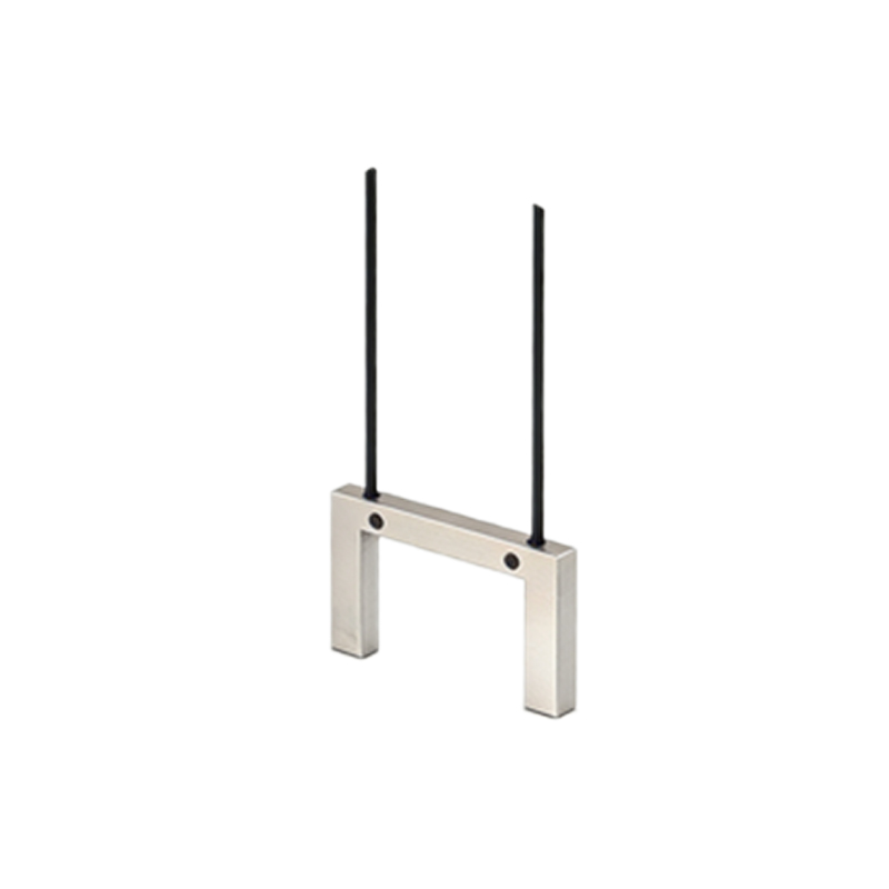
Key Components in the Schematic
A typical photoelectric sensor schematic includes an infrared LED emitter, a phototransistor or photodiode receiver, a comparator IC (e.g., LM393), and a microcontroller interface. The emitter circuit uses a current-limiting resistor to drive the LED at 20 mA, while the receiver circuit amplifies the photocurrent. A potentiometer adjusts the threshold voltage for the comparator, distinguishing between light and dark conditions. For through-beam sensors, the emitter and receiver are separate, while retro-reflective designs use a reflector.
Detailed Circuit Design Process
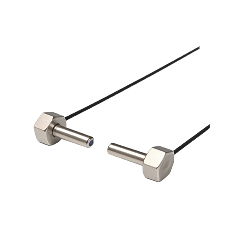
The emitter side consists of a 5V supply, a 220-ohm resistor, and an IR LED connected to a digital output pin of the microcontroller. The receiver uses a phototransistor with a 10k-ohm pull-up resistor to VCC. The output feeds into the non-inverting input of the LM393, with the inverting input set by a 10k-ohm potentiometer as a voltage divider. A 10nF capacitor across the power pins reduces noise. The comparator output goes to the microcontroller's GPIO pin. This design ensures fast response (<1 ms) for conveyor belt applications.
Microcontroller Code for Signal Processing
The following C++ code for Arduino illustrates digital debouncing and state detection. Initialize the sensor pin as input:pinMode(sensorPin, INPUT). In the loop, read the digital value:bool state = digitalRead(sensorPin). Implement a 10-ms delay to debounce:delay(10). Then, compare the new state with the previous one to detect rising or falling edges. For analog sensing, useanalogRead() and a threshold (e.g., 512). The code handles output logic for PLC integration via a relay or transistor.
Code Example for Through-Beam Detection
``cpp
const int sensorPin = 2; // Digital input from comparator
const int ledPin = 13; // Indicator LED
bool lastState = LOW;
void setup() {
pinMode(sensorPin, INPUT);
pinMode(ledPin, OUTPUT);
Serial.begin(9600);
}
void loop() {
bool currentState = digitalRead(sensorPin);
if (currentState != lastState) {
delay(10); // Debounce
if (currentState == HIGH) {
digitalWrite(ledPin, HIGH);
Serial.println("Object detected");
} else {
digitalWrite(ledPin, LOW);
Serial.println("No object");
}
lastState = currentState;
}
}
``
This code ensures reliable detection in noisy industrial environments.
Advanced Considerations for Industrial Use
For long-range applications (>10 meters), use laser diodes and photodetectors with automatic gain control. Shield the circuit with a metal enclosure to reduce electromagnetic interference (EMI). Implement watchdog timers in code to reset the sensor during faults. Calibration can be automated using a potentiometer with a servo motor, adjusting thresholds via I2C communication. Always reference IPC-2221 for PCB design rules to ensure thermal management and signal integrity.
Testing and Troubleshooting Tips
Test the sensor with a multimeter: measure voltage across the phototransistor (should swing from 0.2V to 4.8V). If output is unstable, add a 100nF capacitor to the comparator's output. For code issues, use serial monitor to log raw ADC values. Common problems include ambient light interference, which can be mitigated by modulating the LED at 38 kHz and using a band-pass filter in the receiver circuit.
Conclusion
Mastering photoelectric sensor schematic and code design empowers engineers to create custom automation solutions. By following the circuit and code patterns above, you can develop robust sensors for manufacturing, logistics, and safety systems. Always adapt these designs to your specific voltage and environmental requirements, ensuring compliance with IEC 60947-5-2 standards for industrial sensors.