Understanding the Basics of Infrared Photoelectric Sensors
Infrared photoelectric sensors are critical components in industrial automation, used for object detection without physical contact. They consist of an emitter, which sends out infrared light, and a receiver, which detects the reflected or interrupted beam. Before wiring, identify the sensor type: through-beam, retro-reflective, or diffuse. Each type affects wiring configuration due to differences in power and signal requirements. Typically, sensors come with color-coded wires: brown for power (+V), blue for ground (0V), and black for output (NO or NC). Some models include white for alarm or test functions. Always verify the datasheet to match wire functions with the intended PLC or relay input.
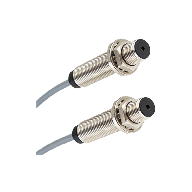
Step-by-Step Wiring Procedure for a 3-Wire DC Sensor
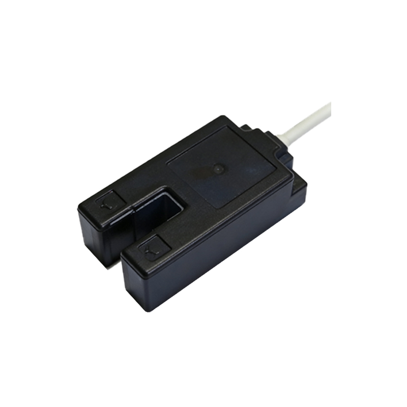
Start by cutting power to the circuit to avoid electrical hazards. Connect the brown wire to a DC power supply positive terminal, typically 12-24V DC, as per sensor specifications. Attach the blue wire to the power supply negative or ground. The black wire serves as the output, which should be linked to the input of a programmable logic controller (PLC) or a relay coil. For a normally open (NO) configuration, the output becomes active when the sensor detects an object; for normally closed (NC), it is active when no object is present. Use a multimeter to verify continuity and voltage levels before powering on. For sensors with a white wire, connect it to the common line or use it for alarm output, depending on the application. Secure all connections with proper terminal blocks or soldering, and apply heat shrink tubing for insulation.
Wiring Considerations for 4-Wire and AC Sensors
For 4-wire sensors, an additional wire is often used for complementary output, such as both NO and NC signals. Wire the brown and blue as before, then connect the black wire to the NO output and the white wire to the NC output. These can feed separate PLC inputs for dual-status monitoring. For AC-powered sensors, the wiring differs: typically, brown and blue wires connect to the AC line and neutral, respectively, while the output wire (often black) switches the load. Ensure the load does not exceed the sensor’s rated current. Use a relay for high-current applications. Always consider cable length and electromagnetic interference—shielded cables are recommended for runs over 10 meters.
Testing and Troubleshooting the Sensor Connection
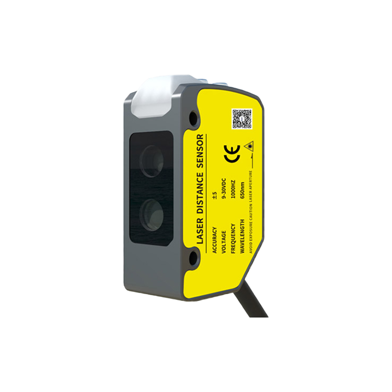
After wiring, power on the system and test the sensor’s operation. Place a target object in the detection zone and observe the output indicator light on the sensor (if present). Use a PLC diagnostic tool or a test lamp to confirm signal changes. Common issues include incorrect wire polarity, which can damage the sensor, or loose connections causing intermittent signals. Check the supply voltage with a multimeter—it should be within the sensor’s rated range (+/-10%). If the sensor fails to respond, inspect the lens for dirt or misalignment, especially in through-beam types. For retro-reflective sensors, ensure the reflector is clean and properly aligned. If persistent, replace the sensor or consult the manufacturer’s support.
Safety and Best Practices for Industrial Wiring
Always follow lockout/tagout procedures during installation. Use appropriate personal protective equipment (PPE), such as insulated gloves and safety glasses. Avoid running sensor cables parallel to high-voltage power lines to prevent noise interference. Label all wires at both ends for future maintenance. Implement surge protection devices if the sensor is near heavy machinery. Document the wiring schematic in the system’s manual for reference. For outdoor or harsh environments, use sensors with IP67 or higher ratings and ensure sealed conduit connections. Regular inspection of wiring for corrosion or wear is essential for long-term reliability.