Proper wiring of a conveyor belt laser sensor is crucial for ensuring accurate detection, stable operation, and long-term reliability in industrial automation systems. These sensors, often used for object detection, positioning, or counting on moving production lines, rely on precise electrical connections to function correctly. Incorrect wiring can lead to sensor failure, inaccurate readings, or even damage to the sensor or connected machinery. This guide provides a clear, step-by-step approach to wiring a typical laser sensor for conveyor applications, focusing on safety, best practices, and common configurations.
Before starting any wiring work, the first and most critical step is to ensure complete electrical safety. Always disconnect and lock out all power sources to the conveyor system and control panel. Verify that no voltage is present using a appropriately rated multimeter. Gather the necessary tools: wire strippers, crimping tools, screwdrivers, and the sensor's datasheet or manual. The datasheet is your essential reference, as it contains the specific wiring diagram, voltage requirements, pin assignments, and output specifications for your exact sensor model. Never proceed without consulting it.
Most industrial laser sensors for conveyors have a compact housing with a built-in cable or a connector port. Models with a pre-attached cable typically have several color-coded wires. Common wire colors and their functions include: Brown wire for the positive DC supply voltage (often +10 to +30 VDC), Blue wire for the DC common or 0V (ground), Black wire for the normally open (NO) output signal, White wire for the normally closed (NC) output signal, and sometimes a Green/Yellow wire for a dedicated ground or shield. Sensors with connector ports (e.g., M8 or M12 connectors) require a matching plug that you wire separately. The core principle remains the same: connecting power and the output signal to the correct points in your control system.
The standard wiring procedure involves three main circuits: the power supply circuit, the output load circuit, and optionally, a grounding/shielding circuit. For the power supply, connect the sensor's Brown wire to the positive terminal of your DC power source (e.g., +24 VDC from the PLC or a separate power supply). Connect the sensor's Blue wire to the negative or 0V terminal of the same DC source. This provides the energy for the sensor's internal laser and electronics.
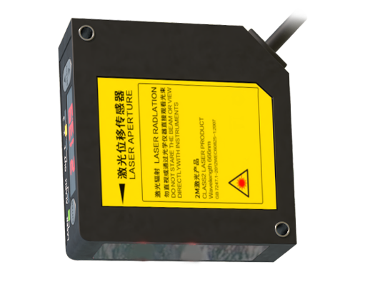
Next, wire the output. A laser sensor is essentially a switch controlled by light. Its output wires connect to the device that needs the detection signal, such as a Programmable Logic Controller (PLC) input module, a relay, or an indicator. If you need the output to be "ON" (conducting) when an object is detected, use the Black wire (NO). Connect one end of this wire to the sensor's output terminal (if labeled) or follow the diagram. The other end connects to your load (e.g., one terminal of a PLC digital input). The other side of that PLC input is then connected back to the positive supply (+24 VDC) or the 0V, depending on whether your PLC uses sinking or sourcing input logic. This forms a complete circuit. When the sensor detects an object, its internal switch closes, allowing current to flow through this circuit and signaling the PLC. For a signal that is "ON" when no object is present, use the White wire (NC) instead.
Grounding is vital for electrical noise immunity, especially in industrial environments with motors and variable frequency drives. Connect the sensor's metal housing or dedicated ground wire (Green/Yellow) to a solid earth ground point on the control panel using a separate wire. If the sensor cable has a shield, connect the shield braid only at one end (typically the control panel end) to the ground terminal to prevent ground loops.
After wiring, double-check every connection against the datasheet diagram. Ensure wires are securely tightened in terminals and that no stray strands could cause a short circuit. Once verified, you can apply power. Many sensors have a visible LED indicator that shows power status and detection state. Test the sensor by passing an object on the conveyor through its laser beam. Observe the output LED and verify the corresponding signal appears in your PLC or control system. Adjust the sensor's sensing distance or sensitivity if necessary, following its manual.
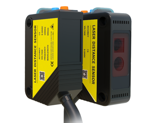
Common wiring mistakes to avoid include: applying AC power to a DC-only sensor (or vice-versa), confusing the Brown and Blue power wires (which can destroy the sensor), over-tightening terminal screws and damaging wire strands, neglecting to connect the shield for noise-prone environments, and mismatching the output type (e.g., connecting an NPN sensor output to a sinking PLC input without proper configuration). Taking your time to plan and execute the wiring correctly will ensure your conveyor laser sensor provides reliable, maintenance-free service for years, forming a dependable component of your automated production line.