Understanding Photoelectric Sensors in Conveyor Systems
Photoelectric sensors are critical components in modern conveyor belt systems, used to detect the presence, position, or absence of objects without physical contact. In industrial environments, these sensors rely on light beams (visible or infrared) to trigger control signals. The control end, often integrated with a PLC (Programmable Logic Controller), interprets the sensor output to start, stop, or adjust belt speed. Proper calibration ensures reliable operation, preventing jams or missed detections in high-speed production lines.
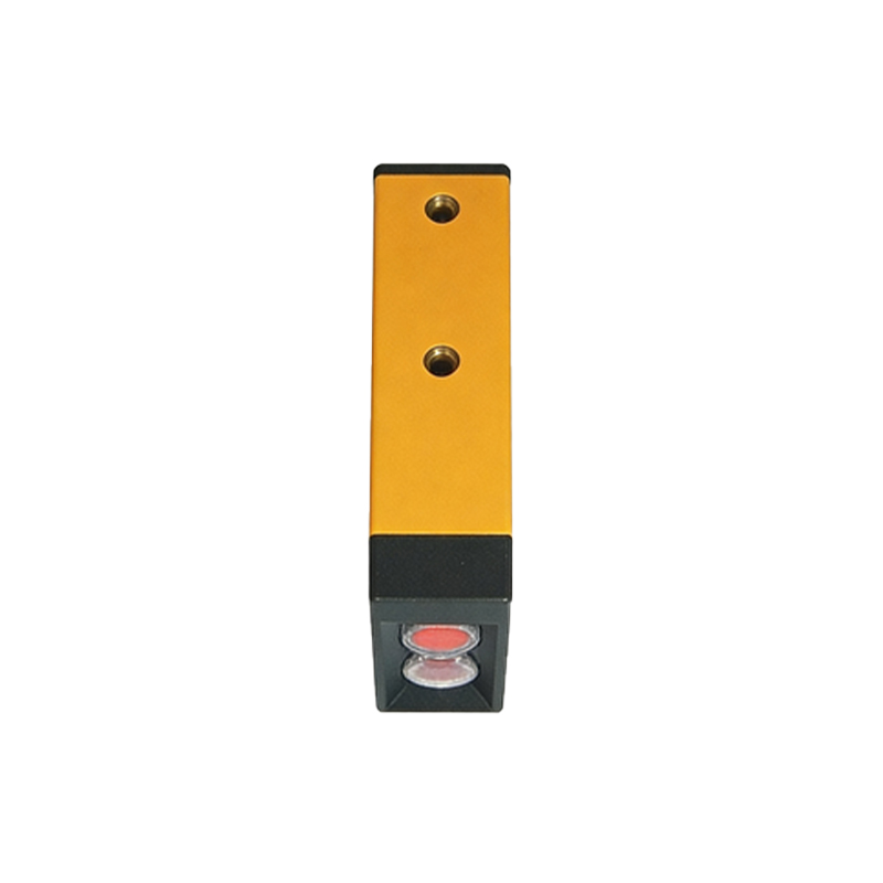
Key Components of the Control End Circuitry
The control end of a photoelectric sensor typically includes a power supply module, a signal processor, and an output interface. For conveyor belt applications, the sensor's output can be NPN (sinking) or PNP (sourcing), which must match the PLC input requirements. Engineers must consider wiring diagrams, ensuring correct polarity and shielding against electromagnetic interference (EMI). A typical setup uses a 24V DC supply, with a relay or transistor switch to activate the belt motor controller. Regular inspection of connectors and cable insulation is vital to maintain signal integrity.
Configuring Sensitivity and Response Time
Optimizing the sensor's sensitivity is crucial for minimizing false triggers. Adjusting the potentiometer on the sensor's control end allows fine-tuning based on object size, color, and speed. For example, transparent or dark-colored items might require a higher gain setting. Response time, often measured in milliseconds, should match the belt speed; a slower response may cause objects to be missed, while an overly fast response can lead to erratic signals. Use an oscilloscope or diagnostic tool to verify the sensor's pulse width and delay.
Integrating with PLC for Automated Control
The sensor's control end sends a digital signal to the PLC, which executes logic commands. A common scenario is detecting a product at a specific point to activate a diverting arm or stop the belt. Ladder logic programming includes timers and counters to handle multiple sensor inputs. For example, if two sensors confirm an object's position, the PLC triggers a pneumatic actuator. Ensure the sensor's output current rating (e.g., 100 mA) does not exceed the PLC's input capacity; use an intermediate relay if necessary.
Troubleshooting Common Control End Issues
Frequent problems include signal dropout, false pulses, or complete failure. Check for dust or oil on the lens, which attenuates the light beam. Verify the power supply voltage at the control end with a multimeter; even a 10% drop can disrupt operation. Oscillations or flickering may indicate a loose connection or interference from nearby motors. Replace damaged cables with shielded types, and ensure the grounding is solid. Document all adjustments for maintenance records.
Future Trends in Photoelectric Sensor Control
Advances include IO-Link communication, which enables real-time diagnostics and parameter adjustments from a central system. Smart sensors with built-in microcontrollers can self-calibrate for varying conveyor loads. Engineers are also adopting wireless control ends for remote monitoring in hazardous zones. These innovations reduce downtime and improve efficiency, making photoelectric sensors even more integral to Industry 4.0 conveyor automation.