Understanding Photoelectric Sensors in Motor Control
Photoelectric sensors are critical components in modern motor control systems, enabling precise detection of objects, positions, and motion without physical contact. In electrical engineering, these sensors use light beams to detect presence, absence, or distance, often interfacing with motor drives, PLCs, and relays. Common types include through-beam, retro-reflective, and diffuse sensors, each requiring distinct wiring configurations. For instance, a through-beam sensor consists of a separate emitter and receiver, necessitating two pairs of wires for power and signal transmission. Proper wiring ensures reliable operation, minimizes electrical noise, and prevents false triggering in industrial environments.
Standard Wiring Color Codes and Connections
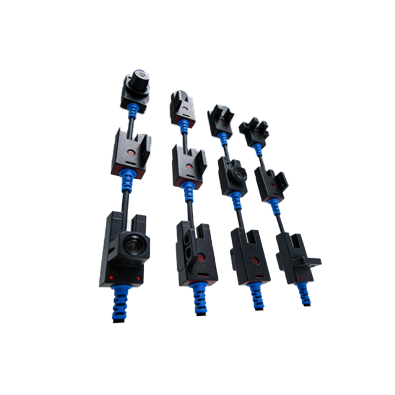
When integrating photoelectric sensors with motors, adhere to standardized color codes to avoid errors. Typically, brown wire is for positive power supply (DC 10-30V), blue for negative (0V), and black for output signal (NPN or PNP). For AC sensors, wires may include brown (line), blue (neutral), and black (output). In motor applications, the output wire connects to a motor starter coil, variable frequency drive (VFD) input, or PLC digital input. Ensure power supply voltage matches sensor specifications; using a 24V DC sensor on a 120V AC circuit can cause permanent damage. Always refer to the manufacturer datasheet for exact pinouts.
Wiring Diagram for NPN vs. PNP Sensor Outputs
Photoelectric sensors commonly feature NPN (sinking) or PNP (sourcing) outputs. In an NPN configuration, the output sinks current to ground when triggered, while PNP sources current to the load. For motor control, PNP sensors are preferred in North America due to compatibility with standard PLC inputs. A typical wiring diagram includes: connect brown to 24V DC, blue to 0V, and black to the motor relay coil’s positive terminal. Use a pull-down resistor (e.g., 10kΩ) for NPN outputs to ensure stable signal levels. Include a flyback diode across inductive loads like motor contactors to suppress voltage spikes.
Common Wiring Mistakes and Troubleshooting
Common errors include reversed polarity, mismatched output types, and incorrect load connections. For example, connecting a PNP sensor to an NPN input can cause no response or erratic behavior. Use a multimeter to verify voltage at sensor terminals: brown should read 24V DC relative to blue. If the output signal fails, check for loose connections, damaged cables, or optical obstruction. In motor applications, electromagnetic interference (EMI) can affect sensor signals; use shielded twisted-pair cables and ground the shield at one end only. Test sensor alignment by moving the target object and observing the LED indicator on the sensor.
Integration with VFDs and PLCs for Automation
To integrate photoelectric sensors with variable frequency drives (VFDs) or PLCs, follow a structured approach. For a VFD, connect the sensor output to a digital input terminal, such as DI1, and configure the drive to stop or reverse motor on object detection. Use a 2-wire sensor for simple on/off control, or a 4-wire sensor for complementary outputs (NO/NC). In PLC systems, map the sensor to an input module, e.g., I:1/0, and program logic to control motor speed. Always include a delay filter in software to debounce sensor signals and prevent false triggers from vibration or dust.
Safety and Maintenance Best Practices
Safety is paramount when working with motor photoelectric sensor wiring. De-energize all circuits before installation or maintenance. Use lockout/tagout procedures. Inspect sensor lenses regularly for dust, oil, or condensation, which can impair detection. For harsh environments, select IP67-rated sensors and use conduit to protect wiring. Document wiring diagrams in maintenance logs and label all connections clearly. Perform periodic functional tests by simulating object presence and verifying motor response. Replace sensors showing erratic behavior promptly to avoid production downtime.