Understanding the Basics of Photoelectric Sensors and Relays
In industrial automation, photoelectric sensors detect the presence or absence of objects using light beams, while relays act as electromechanical switches to control larger loads. When connecting a photoelectric sensor to a relay, the key is to ensure proper voltage matching and wiring polarity. Most photoelectric sensors output a DC signal, typically 10-30V DC, while relays require a coil voltage that matches the sensor's output. Always consult the sensor datasheet to determine if it is a PNP (sourcing) or NPN (sinking) type, as this dictates the wiring configuration. For example, a PNP sensor provides a positive output to the relay coil, whereas an NPN sensor connects the load to ground.
Wiring a PNP Photoelectric Sensor to a Relay
For a PNP sensor, connect the brown wire to the positive supply voltage (e.g., +24V DC), the blue wire to the negative supply (0V), and the black wire (output) to one terminal of the relay coil. The other terminal of the relay coil must be connected to the negative supply. When the sensor detects an object, it switches the output to positive, energizing the relay. Ensure the relay coil voltage matches the sensor's output voltage, typically 24V DC. Use a flyback diode across the relay coil to suppress voltage spikes, which can damage the sensor. The diode should be oriented with the cathode (marked end) connected to the positive side of the coil.
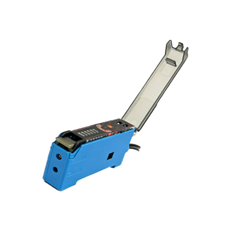
Wiring an NPN Photoelectric Sensor to a Relay
An NPN sensor operates differently: the brown wire connects to positive supply, blue to negative, and the black output wire connects to one relay coil terminal. The other relay coil terminal must be connected to the positive supply. When the sensor detects an object, it pulls the output to ground, completing the circuit through the relay coil. This is often called a "sinking" configuration. As with PNP sensors, always add a flyback diode across the relay coil to protect the sensor from back-EMF. Check the sensor's current rating to ensure it can handle the relay coil's inrush current—typically 50-100 mA for standard industrial relays.
Common Mistakes and Troubleshooting Tips
A frequent issue is using the wrong power supply voltage, which can damage the sensor or prevent the relay from latching. Verify the sensor's operating voltage range and relay coil voltage before powering up. Another mistake is forgetting the flyback diode, which leads to sensor failure due to voltage spikes. If the relay chatters or fails to engage, check for loose connections or incorrect wiring polarity. Use a multimeter to measure voltage at the sensor output when activated: it should read close to the supply voltage for PNP or near 0V for NPN. Lastly, ensure the sensor's load current (max 100-200 mA) is sufficient to drive the relay coil; if not, use an intermediate solid-state relay.
Practical Application Example: Conveyor Belt Control
Consider a conveyor belt system where a photoelectric sensor detects a box and triggers a relay to activate a solenoid valve. Use a 24V DC PNP sensor with a 24V DC relay. Wire the sensor's brown wire to +24V, blue to 0V, and black to the relay coil terminal A1. Connect terminal A2 to 0V. Add a flyback diode (e.g., 1N4007) across the relay coil, cathode to A1. When the box interrupts the sensor's light beam, the output goes high, energizing the relay, which then switches the solenoid valve. This setup is robust for dusty environments, provided the sensor is properly aligned and cleaned regularly.