Introduction to Photoelectric Sensors
Photoelectric sensors are essential components in industrial automation, used to detect the presence, absence, or distance of objects without physical contact. These sensors operate by emitting a beam of light, typically infrared or visible, and measuring the changes in the received light. As an electrical engineer, understanding the types and applications of these sensors is crucial for system design and troubleshooting. Below, we analyze example images to illustrate key concepts.
Through-Beam Sensors: A Visual Example
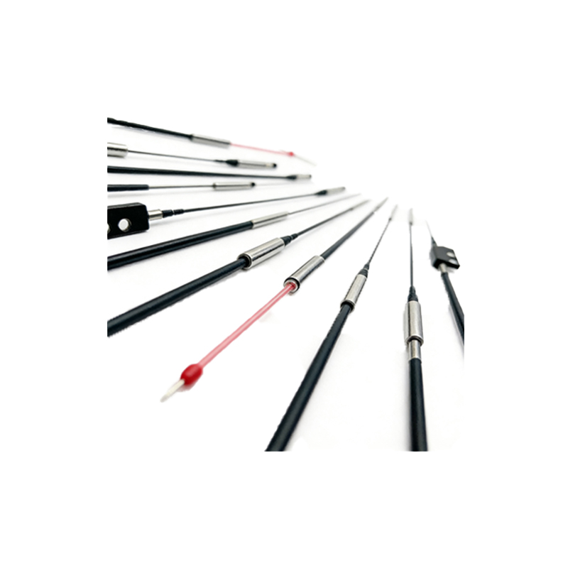
In a through-beam sensor setup, the emitter and receiver are placed opposite each other. An example image shows a clear separation between the two units, with a visible light beam crossing the gap. When an object interrupts this beam, the sensor output changes. This configuration offers the longest sensing range, up to 30 meters in some models, and is immune to target reflectivity. Engineers should note the need for precise alignment, as misalignment can cause false triggers.
Retro-Reflective Sensors in Practice
A retro-reflective sensor example image displays the emitter and receiver housed in a single unit, with a reflector placed opposite. The beam travels from the emitter to the reflector and back to the receiver. The image highlights the reflector's distinct pattern, often made of prismatic material. This design simplifies wiring and reduces installation space, but the sensing range is shorter than through-beam types, typically up to 10 meters. Engineers must consider the target's opacity, as transparent objects may not be detected reliably.
Diffuse Reflective Sensors: Close-Range Detection
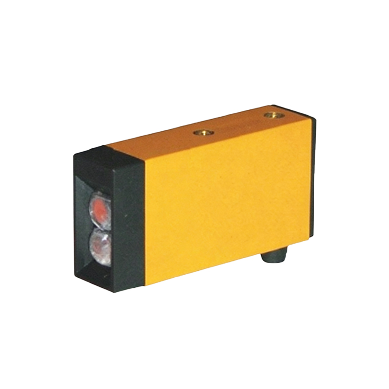
The diffuse reflective sensor example image shows a single housing containing both emitter and receiver, with the beam directed at the target. The image often includes a background object to demonstrate the sensor's limited detection zone. This type relies on light reflection from the target itself, making it ideal for detecting objects within a few meters. Background suppression is a critical parameter; the example image may show how the sensor ignores distant backgrounds, ensuring accurate detection of near objects.
Selection Criteria from Example Images
Analyzing example images helps engineers select the right sensor. Key factors include sensing distance, target material, and environmental conditions. For instance, a through-beam image might show dust or fog interference, advising the use of a high-power LED. The retro-reflective image could illustrate angle sensitivity, prompting consideration of polarization filters. Engineers should always refer to datasheets for specific performance curves, as images alone provide only qualitative insights.
Common Applications and Troubleshooting
Example images often depict real-world applications, such as conveyor belt monitoring or packaging line counting. In a troubleshooting scenario, an image might show a misaligned retro-reflective sensor causing false signals. Engineers can use these visuals to identify issues like lens contamination, light interference, or target surface irregularities. Regular maintenance, including cleaning lenses and checking alignment, is evident from images showing degraded performance over time.
Conclusion: Leveraging Visual Tools
Photoelectric sensor example images are invaluable for educational and practical purposes. They bridge the gap between theoretical specifications and real-world behavior. As an engineer, using these visuals alongside technical documentation enhances your ability to design robust automation systems. Always verify with physical testing, as images cannot replicate dynamic conditions like vibration or temperature variations.