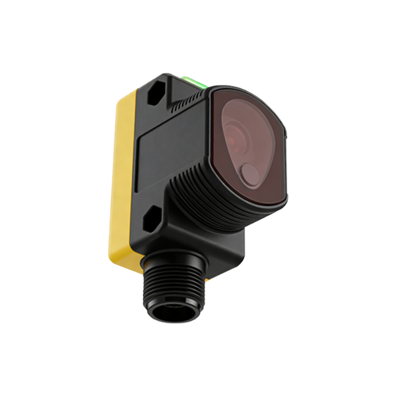
Photoelectric sensors are essential components in modern industrial automation, used to detect the presence or absence of objects through light emission and reception. These sensors convert light signals into electrical signals, enabling precise control in manufacturing lines, packaging systems, and safety applications. Understanding their wiring schematics is critical for engineers and technicians to ensure reliable operation and minimize downtime.
Photoelectric sensors are essential components in modern industrial automation, used to detect the presence or absence of objects through light emission and reception. These sensors convert light signals into electrical signals, enabling precise control in manufacturing lines, packaging systems, and safety applications. Understanding their wiring schematics is critical for engineers and technicians to ensure reliable operation and minimize downtime.
Basic Wiring Principles
Every photoelectric sensor requires three primary connections: power supply (typically 10-30V DC or 24V AC/DC), output signal (NPN or PNP type), and ground (common). The wiring diagram typically includes a brown wire for positive voltage, blue for negative/ground, and black for the output signal. Some models feature additional wires for test inputs or alarm outputs. Always verify the sensor's data sheet for specific voltage and current ratings to avoid damage.
NPN vs. PNP Output Configurations
Choosing the correct output type is vital. NPN (sinking) sensors connect the load between the positive supply and the output wire, switching to ground when activated. Conversely, PNP (sourcing) sensors connect the load between the output and ground, switching to the positive supply. In wiring schematics, NPN outputs are often labeled as "NO" (Normally Open) or "NC" (Normally Closed), while PNP outputs use the same conventions. For example, a PNP NO sensor will output a positive signal only when the target is detected.
DC Wiring Diagram Example
Consider a standard three-wire DC photoelectric sensor. The wiring schematic includes: brown wire connected to +24V DC, blue wire to 0V (ground), and black wire to the input of a PLC (Programmable Logic Controller) or relay. Ensure the PLC input is compatible with the sensor's output type. For PNP sensors, the PLC input should be configured for sourcing inputs; for NPN, sinking inputs. Use a pull-up or pull-down resistor if required to prevent floating states.
AC Wiring Considerations
AC-powered photoelectric sensors (typically 24-240V AC) use two-wire configurations with series-connected loads. The schematic shows one wire for live (L) and one for neutral (N), with the output integrated into the circuit. These sensors often have a built-in thyristor or triac for switching. Pay attention to leakage current, which may cause false triggering in sensitive loads. Always include a snubber circuit for inductive loads.
Four-Wire and Five-Wire Sensors
Advanced photoelectric sensors may include additional wires for features like light/dark select, sensitivity adjustment, or alarm outputs. A four-wire sensor adds a secondary output (e.g., alarm or test), while a five-wire sensor may include a separate shield for noise immunity. In wiring schematics, these extra wires are color-coded per manufacturer standards (e.g., white for alarm, yellow for test). Connect unused wires safely with insulating caps.
Troubleshooting Common Wiring Issues
Common problems include incorrect polarity, mismatched output type, and poor grounding. For instance, reversing the brown and blue wires can damage the sensor. Use a multimeter to verify voltage at the sensor terminals before powering on. Ensure the load resistance falls within the sensor's specified range, especially for two-wire AC sensors. Check for electromagnetic interference (EMI) by routing signal wires away from high-power cables.
Safety and Best Practices
Always follow lockout/tagout procedures when wiring sensors in live systems. Use shielded cables for long runs (>50 meters) to reduce noise. Label all wires clearly and reference the manufacturer's schematic. Test the sensor's output with a known load before integrating into the control system. For hazardous environments, select intrinsically safe sensors and barriers.
Every photoelectric sensor requires three primary connections: power supply (typically 10-30V DC or 24V AC/DC), output signal (NPN or PNP type), and ground (common). The wiring diagram typically includes a brown wire for positive voltage, blue for negative/ground, and black for the output signal. Some models feature additional wires for test inputs or alarm outputs. Always verify the sensor's data sheet for specific voltage and current ratings to avoid damage.
Choosing the correct output type is vital. NPN (sinking) sensors connect the load between the positive supply and the output wire, switching to ground when activated. Conversely, PNP (sourcing) sensors connect the load between the output and ground, switching to the positive supply. In wiring schematics, NPN outputs are often labeled as "NO" (Normally Open) or "NC" (Normally Closed), while PNP outputs use the same conventions. For example, a PNP NO sensor will output a positive signal only when the target is detected.
Consider a standard three-wire DC photoelectric sensor. The wiring schematic includes: brown wire connected to +24V DC, blue wire to 0V (ground), and black wire to the input of a PLC (Programmable Logic Controller) or relay. Ensure the PLC input is compatible with the sensor's output type. For PNP sensors, the PLC input should be configured for sourcing inputs; for NPN, sinking inputs. Use a pull-up or pull-down resistor if required to prevent floating states.
AC-powered photoelectric sensors (typically 24-240V AC) use two-wire configurations with series-connected loads. The schematic shows one wire for live (L) and one for neutral (N), with the output integrated into the circuit. These sensors often have a built-in thyristor or triac for switching. Pay attention to leakage current, which may cause false triggering in sensitive loads. Always include a snubber circuit for inductive loads.
Advanced photoelectric sensors may include additional wires for features like light/dark select, sensitivity adjustment, or alarm outputs. A four-wire sensor adds a secondary output (e.g., alarm or test), while a five-wire sensor may include a separate shield for noise immunity. In wiring schematics, these extra wires are color-coded per manufacturer standards (e.g., white for alarm, yellow for test). Connect unused wires safely with insulating caps.
Common problems include incorrect polarity, mismatched output type, and poor grounding. For instance, reversing the brown and blue wires can damage the sensor. Use a multimeter to verify voltage at the sensor terminals before powering on. Ensure the load resistance falls within the sensor's specified range, especially for two-wire AC sensors. Check for electromagnetic interference (EMI) by routing signal wires away from high-power cables.
Always follow lockout/tagout procedures when wiring sensors in live systems. Use shielded cables for long runs (>50 meters)