Understanding Photoelectric Sensor Test Interference
Photoelectric sensors are widely used in industrial automation for object detection, distance measurement, and position sensing. However, during testing, these sensors can be susceptible to various interference sources, such as ambient light, electrical noise, and reflective surfaces. Interference leads to false readings, reduced accuracy, and system downtime. As an electrical engineer, it is crucial to identify and suppress these disturbances to ensure reliable sensor performance. Common interference types include optical crosstalk from adjacent sensors, electromagnetic interference (EMI) from motors or drives, and environmental factors like dust or fog. The first step is to analyze the test setup and pinpoint the root cause of instability.
Optimizing Sensor Placement and Shielding
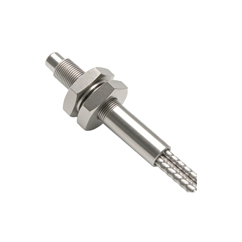
One effective method to suppress interference is to optimize sensor placement and use physical shielding. Position sensors away from high-voltage cables, variable frequency drives, and other EMI sources. Maintain a minimum distance of 30 cm between sensor heads and power lines. Use metal enclosures or shielded cables to block external electromagnetic fields. For optical interference, install baffles or hoods around the sensor to reduce ambient light exposure. In multi-sensor arrays, ensure proper spacing to prevent crosstalk, typically 2-3 times the sensor’s beam diameter. Regular calibration of alignment angles also minimizes false triggers.
Implementing Signal Filtering and Timing Control
Electronic filtering techniques are vital for cleaning sensor output signals. Add low-pass RC filters to the sensor’s signal line to attenuate high-frequency noise from switching power supplies or motor commutation. For digital signals, use Schmitt triggers to eliminate jitter. Timing control, such as synchronized pulsing, can reduce interference in multi-sensor systems. Configure sensors to emit pulses in staggered time slots, preventing overlap. This approach is especially useful in conveyor belt applications where multiple sensors operate simultaneously. Always verify filter cut-off frequencies based on the sensor’s modulation rate to avoid signal loss.
Selecting Appropriate Sensor Modulation and Wavelength
Choosing the right modulation type and wavelength can significantly suppress environmental interference. Modulated sensors with specific pulse frequencies (e.g., 1 kHz to 10 kHz) reject steady-state ambient light, such as sunlight or incandescent lamps. For dusty or humid environments, select infrared (IR) or laser-based sensors with narrow beam angles to reduce scattering. Red light sensors (660 nm) are less affected by water vapor than blue light sensors. In high-EMI areas, use sensors with built-in immunity, such as those compliant with IEC 61000-4-3 standards. Always match the sensor’s response time to the application speed to avoid false triggering from transient noise.
Performing Systematic Grounding and Wiring Practices
Improper grounding is a common source of test interference. Implement a star grounding topology where all sensor shields and power supply grounds connect to a single point, avoiding ground loops. Use twisted-pair cables for signal transmission to cancel induced noise. Separate sensor cables from power cables by at least 15 cm in cable trays. Install ferrite beads on sensor input lines to suppress high-frequency common-mode noise. For long cable runs (over 10 meters), use differential line drivers or current-loop transmitters to maintain signal integrity. Document all grounding points to facilitate troubleshooting.
Conducting Calibration and Environmental Compensation
Regular calibration compensates for drift caused by temperature, aging, or contamination. Use a reference target with known reflectance to adjust sensor thresholds. Implement automatic gain control (AGC) if the sensor supports it, which adapts to gradual changes in ambient light or target distance. For outdoor or harsh environments, add heating elements to prevent lens fogging or condensation. Perform periodic cleaning of sensor optics to remove dust or oil films. After calibration, run a statistical analysis of test results to identify persistent interference patterns and adjust suppression strategies accordingly.