Introduction to Servo Motors and Photoelectric Sensors
In the field of industrial automation, the synergy between servo motors and photoelectric sensors forms the backbone of precision control and reliable operation. As a seasoned electrical engineer, I have observed that these two components are increasingly paired to achieve high-speed positioning, error detection, and adaptive manufacturing processes. Servo motors provide closed-loop control of position, speed, and torque, while photoelectric sensors offer non-contact detection of objects, ensuring system responsiveness and safety.
Core Principles of Servo Motor Operation
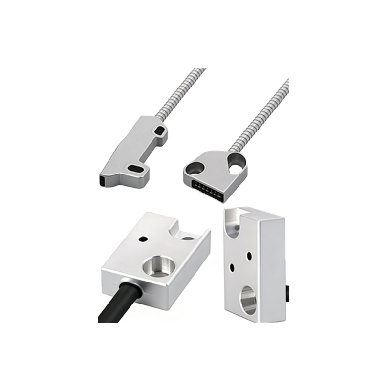
Servo motors operate based on feedback from encoders or resolvers, which continuously monitor the rotor position. The controller compares the actual position with the desired setpoint and adjusts the motor current accordingly. This closed-loop architecture minimizes overshoot and settling time, making servo motors ideal for applications like CNC machining, robotic arms, and conveyor systems. Key parameters include torque constant, inertia ratio, and bandwidth, which must be carefully matched to the load.
Photoelectric Sensor Types and Selection Criteria
Photoelectric sensors are classified into three main types: through-beam, retro-reflective, and diffuse reflective. Through-beam sensors offer the longest range and highest immunity to contamination, while retro-reflective sensors simplify installation by using a reflector. Diffuse sensors are best for detecting objects with varying surface properties. When selecting a sensor, engineers must consider target material, ambient light, response time, and output type (NPN/PNP). For harsh environments, IP67-rated housings and laser-based sensors are recommended.
Integration Strategies for Servo and Sensor Systems
Integrating a photoelectric sensor with a servo drive typically involves connecting the sensor output to a digital input on the drive or PLC. The sensor triggers a start, stop, or homing sequence for the servo axis. For example, in a pick-and-place machine, a through-beam sensor detects the presence of a part and signals the servo to advance. To avoid interference, sensor cables should be shielded and routed separately from power cables. Additionally, using fast-response sensors (less than 1 ms) ensures that the servo can react without lag.
Practical Application: Conveyor Belt Sorting System
A common scenario is a conveyor belt sorting system where multiple servo motors control diverters. Photoelectric sensors are placed at intervals to detect product size, color, or barcode. The sensor sends a signal to the servo controller, which calculates the exact timing to actuate the diverter. This setup reduces product jams and increases throughput. Calibration of sensor thresholds and servo acceleration profiles is critical to maintain accuracy, especially at high belt speeds exceeding 1 m/s.
Maintenance and Troubleshooting Tips
Regular maintenance includes cleaning sensor lenses with isopropyl alcohol and checking servo motor bearings for wear. Common issues include sensor false triggering due to reflective surfaces or misalignment, and servo encoder noise causing position drift. Use an oscilloscope to monitor sensor signals and a servo tuning software to analyze gain settings. If the system exhibits oscillation, reduce the proportional gain or increase the derivative time constant.
Future Trends in Servo-Sensor Integration
Advancements in IO-Link communication enable sensors to transmit diagnostic data directly to the servo drive, allowing predictive maintenance. Additionally, vision-guided servo systems are emerging, where a smart camera replaces multiple sensors. These systems use AI to adapt to changing part geometries, reducing setup time. For engineers, understanding these trends is essential for designing flexible and efficient automation cells.