In press machine applications, photoelectric sensors are vital for safety and automation. A typical 3-wire sensor, either PNP or NPN, uses brown for +24V DC, blue for 0V, and black for the output. For PNP sensors, the black wire sends a positive signal to the PLC when an object is detected. For NPN, the output pulls to ground. Always use shielded cable and separate wiring from high-power lines to reduce noise. Verify connections with a multimeter before powering the system. Troubleshooting should focus on voltage, wire color, and sensor type compatibility. Following these guidelines ensures reliable detection in press operations.
In the press machine industry, photoelectric sensors are critical for safety and automation, often used for detecting material presence, part ejection, or die protection. These sensors operate by emitting a light beam and detecting changes in the reflected or interrupted signal. For a typical press, you will work with a PNP (sourcing) or NPN (sinking) output type, with a three-wire configuration (brown, blue, and black). The choice depends on your PLC input card or relay logic. Always confirm the sensor datasheet for voltage, typically 10-30V DC, to prevent damage.
3. Wiring Diagram for a 3-Wire PNP Photoelectric Sensor
The most common setup for press machines is a PNP normally open (NO) sensor. Connect the brown wire to +24V DC from the power supply. Connect the blue wire to 0V (ground). Connect the black wire to the PLC input terminal or safety relay. When the sensor detects an object, the output switches to +24V, signaling the controller. For a normally closed (NC) variant, the output is active until the target is present. Use a multimeter to verify voltage before energizing the circuit.
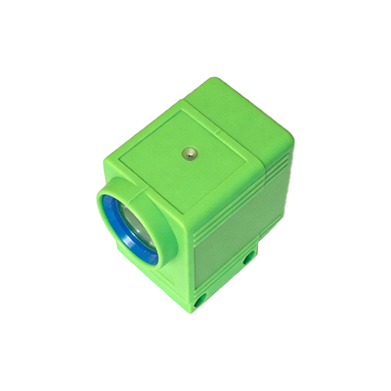
5. Wiring Sequence for NPN Sensor (Less Common but Important)
For NPN sensors, the brown wire still connects to +24V DC, and blue to 0V. However, the black output wire connects to the PLC input and pulls to 0V when active. This requires the PLC input to be configured for sinking signals. In press applications, NPN is often used with older controllers. Ensure isolation to avoid ground loops. Double-check your controller's specification; mismatching PNP/NPN can cause false triggers or no detection.
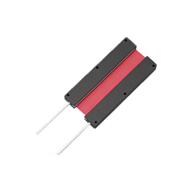
7. Safety and Shielding Considerations for Press Environments
Press machines generate high electrical noise from motors, solenoids, and welding operations. Use shielded twisted-pair cable for the sensor wires, with the shield connected to ground at one end only (PLC side) to prevent ground loops. Keep sensor wiring separate from power cables. Install a fuse on the +24V line to protect against short circuits. For safety-critical press applications (e.g., light curtains), follow the redundant wiring scheme per ANSI B11.19 guidelines.
9. Troubleshooting Common Wiring Issues
If the sensor does not respond, first check the power supply voltage at the sensor terminal block. Next, verify wire continuity with a multimeter. Common mistakes include reversing brown and blue, or using a PNP sensor with a NPN input. For intermittent detection, inspect for loose connections or metal debris interfering with the beam. Use a test target to simulate detection. If the output remains stuck high, the sensor may be damaged or incorrectly configured for NO/NC.