Introduction to Infrared Photoelectric Sensors
Infrared photoelectric sensors are critical components in industrial automation, used for object detection, distance measurement, and presence sensing. Their assembly drawings provide precise specifications for manufacturing, installation, and troubleshooting. These drawings detail the mechanical layout, electrical connections, optical path, and enclosure design to ensure reliable performance in harsh environments.
Key Components in Assembly Drawings
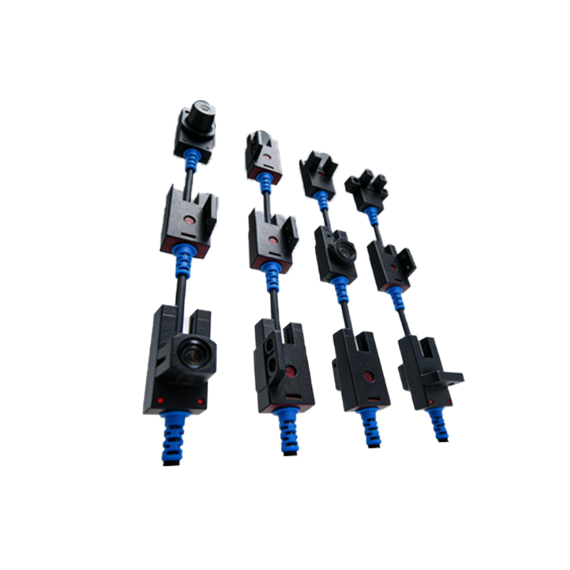
The assembly drawing typically includes the infrared LED emitter, photodiode or phototransistor receiver, lens or reflector system, circuit board with signal processing ICs, and housing with mounting brackets. Each component must be aligned within tight tolerances, typically ±0.1 mm for optical axis accuracy. The drawing also specifies material grades, such as polycarbonate for lenses and aluminum for heat sinks.
Mechanical Layout and Dimensioning
The mechanical section shows the overall dimensions, mounting hole patterns, and clearance requirements. For example, a common through-beam sensor assembly has emitter and receiver units separated by up to 30 meters. The drawing must indicate the beam alignment angle, often within 2 degrees, and provide guidelines for vibration resistance (e.g., 10-55 Hz at 0.35 mm amplitude per IEC 60068-2-6).
Electrical and Wiring Diagrams
The electrical part of the drawing includes the power supply connections (e.g., 12-24 VDC), output types (NPN/PNP, analog, or relay), and protection circuits (reverse polarity, overcurrent). For a retroreflective sensor, the diagram shows the synchronization between emitter and receiver pulses. All wire colors and pin assignments follow IEC 60947-5-2 standards, ensuring compatibility with PLCs and controllers.
Optical Path and Calibration Notes
The optical path diagram illustrates the infrared beam (typically 850 nm or 940 nm) reflecting off a reflector or target. The drawing must specify the minimum detectable object size (e.g., 1 mm at 100 mm distance) and ambient light immunity (up to 50,000 lux). Calibration instructions, such as adjusting the potentiometer for sensitivity, are included for field setup.
Enclosure and Environmental Protection
Assembly drawings detail the enclosure IP rating (e.g., IP67 for dust and water ingress), sealing gaskets (silicone or EPDM), and cable gland specifications. For outdoor use, the drawing may recommend UV-stable materials and anti-fog coatings on lenses. Thermal management is addressed through ventilation slots or heat sinks, ensuring operation from -25°C to +70°C.
Troubleshooting and Maintenance Notes
The final section of the drawing provides common failure modes, such as misalignment due to thermal expansion or dirt accumulation on lenses. It recommends periodic cleaning with isopropyl alcohol and a lint-free cloth. Inspection intervals are suggested every 6 months or 10,000 hours of operation, with alignment checks using a laser pointer tool.