Introduction to Photoelectric Sensors in Brightness Detection
Photoelectric sensors play a critical role in industrial automation systems by converting light intensity into measurable electrical signals. For brightness acquisition, these sensors typically employ photodiodes, phototransistors, or photoresistors (LDRs) to detect variations in ambient or target-reflected light. The key advantage lies in their non-contact operation, high sensitivity, and rapid response time, making them ideal for applications like conveyor belt sorting, LED panel calibration, or liquid clarity monitoring. Engineers must carefully select sensor types based on wavelength range, environmental noise, and required resolution to ensure reliable brightness data.
Sensor Selection Criteria for Brightness Measurement
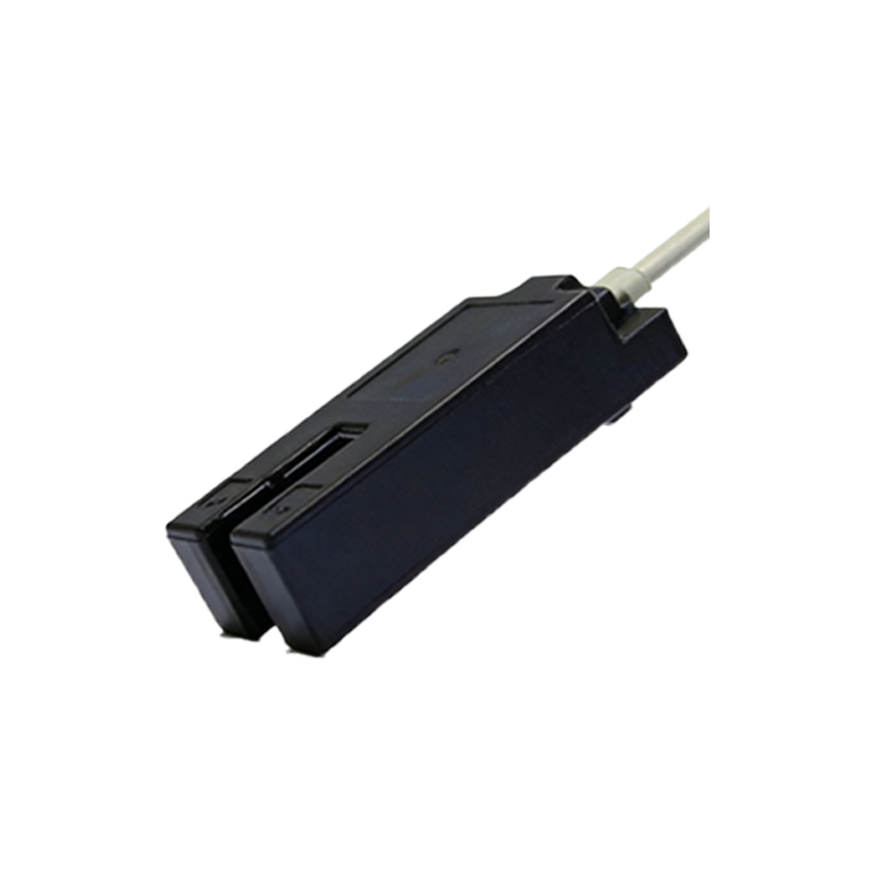
When designing a brightness acquisition system, three primary factors dictate sensor choice: spectral sensitivity, linearity, and ambient immunity. For visible light, silicon-based photodiodes offer excellent linearity and fast response, while phototransistors provide higher gain for low-light scenarios. Infrared sensors are preferred for dark environments or through-opaque-surface detection. Engineers should also evaluate the sensor's angular response, as wide angles may reduce brightness accuracy in focused applications. For demanding industrial settings, shielded photoelectric sensors with built-in amplifiers and filters minimize interference from EMI or stray light.
Circuit Design for Accurate Brightness-to-Signal Conversion
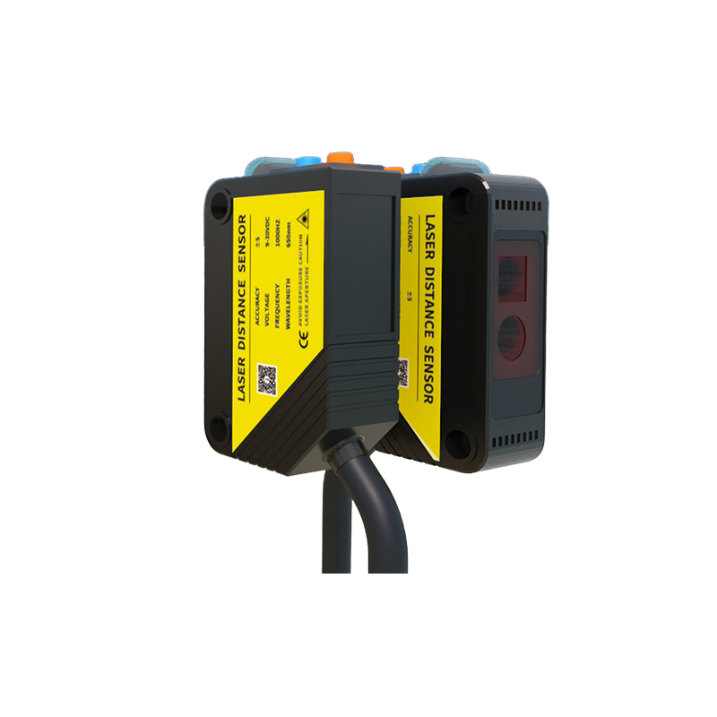
The acquisition circuit must amplify the sensor's photocurrent while rejecting noise. A transimpedance amplifier (TIA) configuration is standard for photodiodes, converting current to voltage with a gain set by the feedback resistor. For phototransistors, a fixed-bias or emitter-follower stage works well. To improve accuracy, use a differential amplifier to cancel common-mode noise, and incorporate a low-pass filter with a cutoff frequency below 50 Hz to suppress 60 Hz power line interference. Additionally, a temperature-compensated reference voltage ensures stable output across -20°C to 85°C industrial ranges.
Calibration and Environmental Compensation
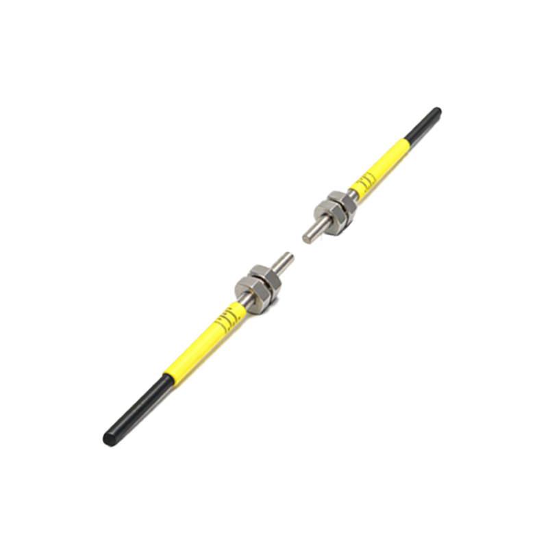
Field calibration is essential to map sensor voltage to absolute brightness units (e.g., lux or cd/m²). Use a calibrated reference light source (e.g., integrating sphere with known luminance) to establish a transfer curve. For dynamic environments, implement adaptive thresholds that adjust for daylight variations or dust accumulation on sensor windows. In multi-sensor arrays, cross-calibration reduces disparities caused by component tolerances. Engineers should also log calibration data in non-volatile memory to enable automatic recalibration upon system startup.
Digital Processing and Output Interfaces
Once analog brightness signals are captured, digitization via an ADC (12-bit or higher) enables precise data logging and control. Process the digitized values using a moving average filter to smooth transients, then compare against setpoints for on/off or proportional output. Common industrial interfaces include 4-20 mA current loops for long-distance transmission, Modbus RTU for PLC integration, or I²C/SPI for local microcontrollers. For real-time feedback, use PWM output where duty cycle directly represents brightness level, enabling direct LED dimming or motor speed control.
Troubleshooting Common Brightness Acquisition Issues
Typical problems include signal drift due to temperature changes, saturation from excessive light, and jitter from intermittent reflections. To diagnose, first verify sensor biasing and shielding integrity. Use an oscilloscope to check for 50/60 Hz hum or high-frequency noise. If readings are erratic, inspect the lens for debris and recalibrate the zero-point offset. For nonlinear behavior, confirm that the sensor's dynamic range matches the target brightness span (e.g., 0-1000 lux vs. 0-10000 lux). Always maintain a clean optical path and use conformal coating on PCBs in humid or corrosive environments.
Future Trends in Photoelectric Brightness Sensing
Advances in smart sensors integrate on-chip DSP for real-time noise cancellation and self-diagnostics. Industry 4.0 demands wireless brightness nodes with LoRa or Bluetooth 5.0 for predictive maintenance. Additionally, multispectral sensors now separate RGB or UV brightness components, enabling color-aware sorting or UV curing monitoring. Engineers should prepare for edge computing architectures where preprocessed brightness data reduces cloud dependency. The transition to TOF (Time-of-Flight) photoelectric sensors also offers precise distance-aware brightness measurement in 3D LiDAR systems.