Introduction to Slot-Type Photoelectric Sensors
Slot-type photoelectric sensors, also known as fork sensors, are essential components in industrial automation. They consist of a transmitter and receiver housed in a single body, forming a U-shaped detection area. These sensors are widely used for object detection, counting, and positioning in conveyor systems, packaging machinery, and assembly lines. A critical aspect of their installation is understanding the wiring configurations, particularly the three-wire and four-wire systems, which determine how the sensor interfaces with controllers like PLCs.
Three-Wire Configuration: NPN and PNP Outputs
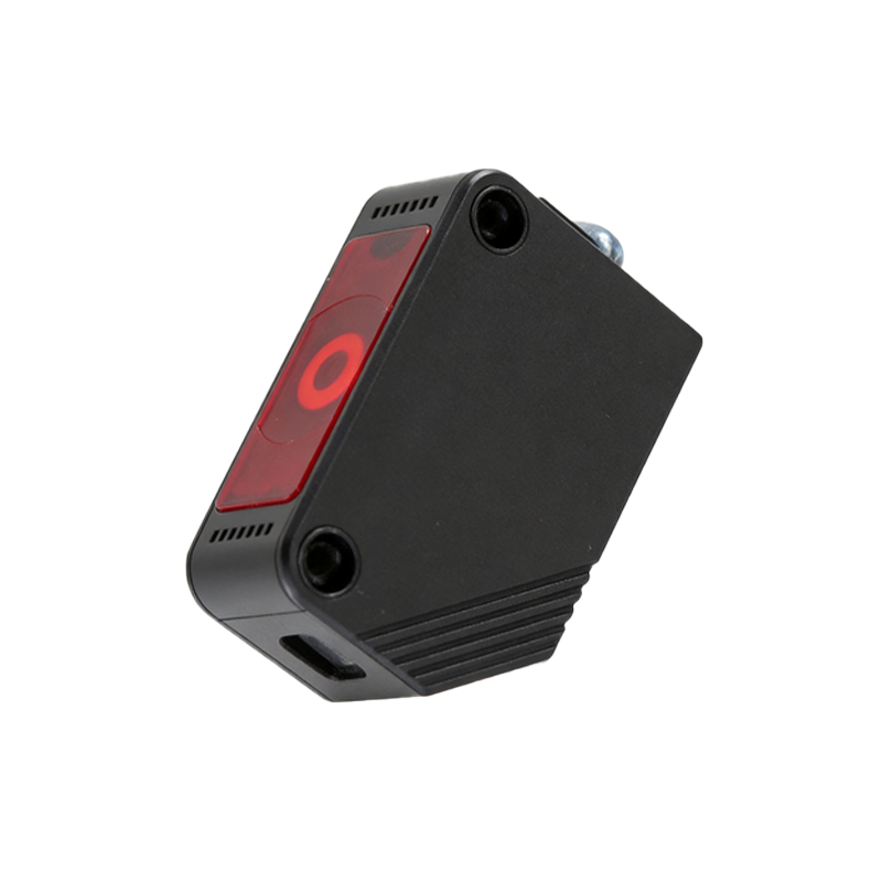
The three-wire configuration is the most common in slot-type photoelectric sensors. It typically includes three leads: power supply positive (brown), power supply negative (blue), and output signal (black). This setup supports two output types: NPN (sinking) and PNP (sourcing). In NPN output, the signal wire switches to ground when an object is detected, suitable for sinking input PLCs. In PNP output, the signal wire connects to the positive supply, ideal for sourcing input controllers. Engineers must select the correct output type based on the load or controller requirements to ensure proper signal transmission and avoid damage.
Four-Wire Configuration: Complementary Outputs
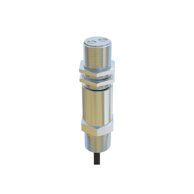
Four-wire slot-type photoelectric sensors offer advanced functionality with two output lines: one normally open (NO) and one normally closed (NC). The wiring includes brown (positive), blue (negative), black (NO output), and white (NC output). This configuration provides complementary signals, meaning when the sensor detects an object, the NO output activates while the NC output deactivates, and vice versa. This is beneficial for applications requiring fail-safe logic, such as safety interlocks or dual-channel monitoring. It also allows direct connection to two separate inputs without external inverters.
Wiring Best Practices for Industrial Environments
When wiring slot-type photoelectric sensors, always follow the manufacturer's datasheet to identify lead colors and output types. Use shielded cables to minimize electromagnetic interference, especially in noisy factory settings. Ensure proper power supply voltage (typically 10-30V DC) and current rating (usually 100-200mA max). For three-wire sensors, connect the output to a PLC input module with matching sinking/sourcing characteristics. For four-wire sensors, verify that both NO and NC outputs are not shorted to each other or to ground. Test the sensor with a multimeter to confirm correct operation before finalizing the installation.
Troubleshooting Common Wiring Issues
Common problems include incorrect output type selection, reverse polarity, or loose connections. If a sensor fails to trigger, check the LED indicator on the sensor body; a steady light often means power is present but output is not switching. Use a multimeter to measure voltage between the output and ground (for NPN) or between output and positive (for PNP) during detection. For four-wire sensors, verify that the NO and NC outputs are complementary; if both are high or low simultaneously, the sensor or wiring is faulty. Always refer to the technical manual for specific troubleshooting steps.
Application Examples in Automation Systems
In a packaging line, three-wire PNP sensors detect product presence on a conveyor, sending signals to a PLC to activate a pusher. Four-wire sensors are used in elevator door systems to monitor the gap; the NO output signals door open, while NC output signals door closed, ensuring safe operation. Another example is in printing presses, where sensors count sheets—three-wire NPN configurations are preferred for compatibility with older PLC models. Selecting the right wiring reduces installation time and improves system reliability.