Overview of LA268 Photoelectric Sensor
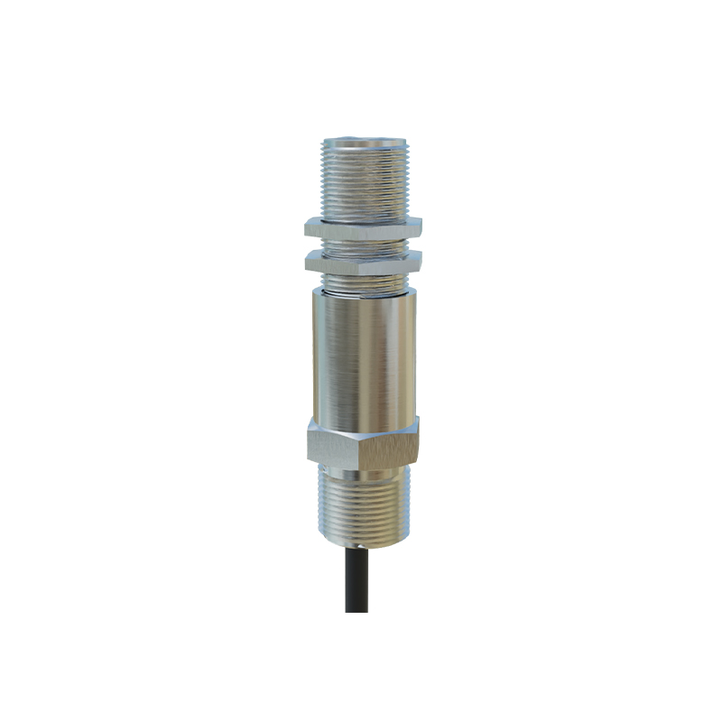
The LA268 photoelectric sensor is a widely used industrial component in automation systems, designed for non-contact detection of objects. Manufactured by key industry players, this model operates based on a modulated infrared light beam, ensuring reliable performance in harsh environments. The circuit diagram of the LA268 is essential for troubleshooting, maintenance, and integration into larger control systems. In this article, we will dissect the key components and functional blocks of the LA268 circuit, providing clarity for engineers and technicians.
Power Supply and Regulation Section
The circuit begins with a power supply stage that converts an external DC voltage, typically 10-30 VDC, into a stable internal rail. This section includes a reverse polarity protection diode, a transient voltage suppressor, and a linear voltage regulator. The regulator output is usually 5 VDC, powering the microcontroller and signal processing logic. Capacitors are placed at the input and output to filter noise, as seen in the LA268 schematic, where a 10 µF electrolytic and a 0.1 µF ceramic are common. Ensure the power supply is clean to avoid false triggering.
Emitter and Modulator Circuit
The emitter section drives an infrared LED at a specific frequency, typically 1 kHz to 10 kHz, to avoid interference from ambient light. A transistor switch, often a NPN type, controls the LED current, with a series resistor limiting the forward current to around 20-50 mA. The modulator circuit generates a square wave using an oscillator IC or a dedicated timer, such as the NE555. The LA268 uses a crystal-controlled oscillator for stability, as indicated in the diagram by a 4 MHz crystal connected to the microcontroller. This modulation ensures the sensor can distinguish its own beam from external noise.
Receiver and Signal Conditioning
On the receiver side, a photodiode or phototransistor captures the reflected or transmitted infrared signal. The received signal is weak and must be amplified. The LA268 circuit includes a transimpedance amplifier stage, converting the photocurrent into a voltage. A high-pass filter removes DC components from ambient light, while a bandpass filter isolates the modulation frequency. The output of the filter is fed into a comparator, which compares the signal against a set threshold, adjustable via a potentiometer. The comparator output is then digitized by the microcontroller.
Microcontroller and Logic Processing
The core of the LA268 is an 8-bit microcontroller, such as the PIC16F series, which processes the digitized signal. The firmware implements debouncing algorithms to prevent false triggers from noise. It also controls the output driver, which can be NPN open-collector or PNP push-pull, depending on the model variant. The circuit diagram shows the microcontroller pins: VDD and VSS for power, an output pin connected to a transistor, and an input pin for the comparator output. An external EEPROM may be present for storing calibration data.
Output Stage and Protection
The final stage is the output driver, which provides a digital signal (NO or NC) to the PLC or controller. In the LA268, this is typically an open-collector NPN transistor with a pull-up resistor. Short-circuit protection is implemented using a current-sensing resistor and a protection diode. The diagram also includes a status LED indicator, connected through a current-limiting resistor to show sensor operation. For EMC compliance, a ferrite bead and a capacitor are placed at the output cable.
Troubleshooting and Testing Points
Using the LA268 circuit diagram, technicians can identify test points: TP1 at the regulator output (5V), TP2 at the comparator output (digital pulse), and TP3 at the photodiode anode (analog waveform). To verify the emitter, check the LED voltage drop with a multimeter. Common issues include a blown regulator from overvoltage or a faulty photodiode from contamination. Always power down before probing to avoid short circuits.