Introduction to Photoelectric Sensor Circuits
In modern industrial automation, photoelectric sensors serve as critical components for object detection, positioning, and counting. The Yangchun photoelectric sensor circuit is designed with high sensitivity and noise immunity, making it suitable for harsh environments. This article explores the circuit architecture, key parameters, and practical implementation tips for engineers.
Circuit Topology and Core Components
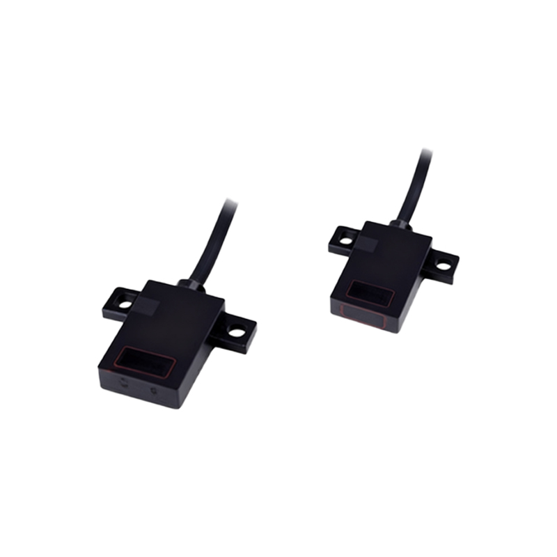
The Yangchun sensor circuit typically employs a modulated infrared LED as the emitter and a phototransistor as the receiver. The emitter circuit uses a 555 timer IC to generate a 38 kHz carrier wave, which improves resistance to ambient light interference. The receiver section includes a bandpass filter tuned to the same frequency, followed by an amplifier stage using operational amplifiers like LM358. A comparator circuit then converts the analog signal into a clean digital output.
Key Performance Parameters
Engineers must consider three critical parameters: sensing distance (typically 0-10 meters for retro-reflective models), response time (under 1 ms), and output current capacity (up to 100 mA). The circuit design includes a hysteresis loop to prevent oscillation near the detection threshold. For long-distance applications, use a collimating lens to focus the beam, but ensure proper alignment to avoid false triggers.
Noise Mitigation Techniques
Industrial environments introduce electrical noise from motors and inverters. To combat this, the Yangchun circuit incorporates a shielded cable for the sensor head and a ferrite bead on the power supply line. The PCB layout should separate analog and digital grounds, with a star grounding topology. Additionally, a low-pass RC filter at the output stage removes high-frequency interference without sacrificing response time.
Practical Application Example
Consider a conveyor belt system where the sensor detects product jams. Connect the sensor's NPN output to a PLC input module. The circuit's adjustable potentiometer sets the threshold level to ignore dust accumulation on the lens. For high-speed lines (over 1000 parts per minute), select a sensor with a fast response time under 0.5 ms. Always include a 10 kΩ pull-up resistor on the output line to ensure logic high when the sensor is inactive.
Testing and Calibration Protocol
Before deployment, perform a bench test using an oscilloscope to verify the waveform integrity at the comparator output. Adjust the sensitivity trimpot until the output transitions sharply at the desired distance. For reflective sensors, use a standard white test card with 90% reflectivity. Record the ambient light levels using a lux meter and adjust the modulation frequency if necessary to avoid interference from building LED lighting.
Maintenance and Troubleshooting Tips
Common failures include lens contamination, cable fatigue, and power supply drift. Clean the lens monthly with isopropyl alcohol and a lint-free cloth. Check the supply voltage at the sensor terminals; it should remain within ±5% of the nominal value. If the output remains high or low, measure the base voltage of the phototransistor; a reading below 0.6 V indicates a dead emitter. Replace the sensor module if the circuit shows persistent oscillation.