Introduction to Photoelectric Sensors
Photoelectric sensors are essential components in industrial automation, using light beams to detect objects, distance, or presence. These sensors operate by emitting a light (typically infrared or visible) and detecting changes in the received light intensity. Engineers must understand the basic circuit design to integrate these sensors effectively into control systems. This guide provides a detailed circuit diagram and a complete component list for a common photoelectric sensor circuit.

Key Circuit Components and Their Functions
A typical photoelectric sensor circuit consists of a light emitter (LED), a photodetector (phototransistor or photodiode), signal conditioning components, and an output stage. The emitter circuit includes a current-limiting resistor to protect the LED. The receiver circuit uses a phototransistor that changes its conduction based on light intensity. A comparator (e.g., LM393) processes the signal, and an output driver (like a transistor or relay) provides the final switch signal.
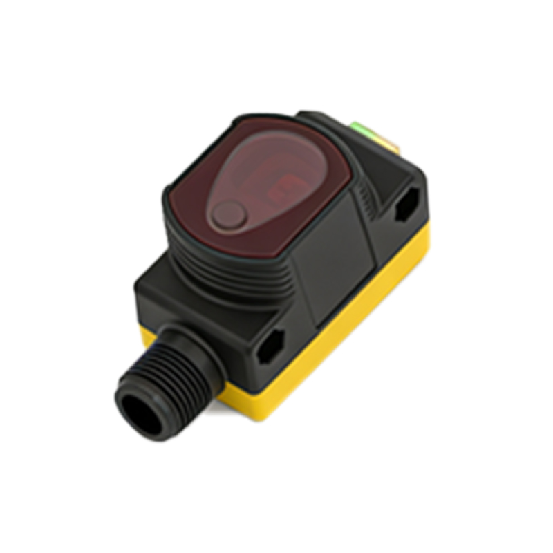
Complete Component List for a Standard Through-Beam Sensor
- Light Emitter Section: IR LED (e.g., TSAL6200), 100 Ohm resistor (R1), 10 uF capacitor (C1) for power filtering.
- Light Receiver Section: NPN phototransistor (e.g., BPW96C), 10k Ohm resistor (R2) as collector load, 100nF capacitor (C2) for noise suppression.
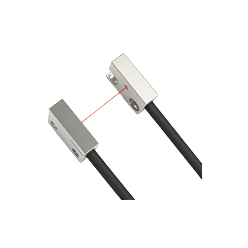
- Signal Processing: LM393 dual comparator IC, 10k Ohm potentiometer (R3) for threshold adjustment, 1k Ohm pull-up resistor (R4) for comparator output.
- Output Section: 2N2222 NPN transistor (Q1) for open-collector output, 1k Ohm base resistor (R5), 1N4007 flyback diode (D1) for inductive load protection.
- Power Supply: 5V DC regulator (7805), 100 uF and 0.1 uF capacitors for input and output decoupling.
Photoelectric Sensor Circuit Diagram Description
The circuit is designed as a through-beam system. The left side shows the emitter: IR LED anode connected to +5V via R1 (100 Ohm), cathode to GND. The right side shows the receiver: phototransistor collector connected to +5V through R2 (10k), emitter to GND. The collector voltage is fed to the non-inverting pin of LM393. A reference voltage from the potentiometer (R3) is applied to the inverting pin. When the light beam is interrupted, the phototransistor turns off, raising the collector voltage above the reference, causing the comparator output to go high. This high signal drives the base of Q1 through R5, turning on Q1 and pulling the output to GND. D1 protects against voltage spikes from inductive loads.
Practical PCB Layout and Wiring Considerations
For reliable operation, keep emitter and receiver circuits separate to avoid optical crosstalk. Use shielded cables for long-distance wiring. Place the comparator and potentiometer close to the receiver. Add a 10 uF electrolytic capacitor near the power input of the LM393. For harsh environments, consider using a 24V DC supply with an additional voltage regulator stage. Always include reverse polarity protection (a diode in series with the power input).
Troubleshooting Common Issues
If the sensor does not trigger, first check the LED emitter - measure voltage across the LED (should be ~1.5V for IR). Use an oscilloscope to look at the phototransistor collector for noise. Adjust the potentiometer to set the threshold midway. If output is unstable, add a 10k pull-up resistor on the comparator output to +5V. For false triggers, increase C2 to 1 uF to filter transient noise.
Conclusion
Understanding the circuit schematic and component roles is crucial for successful photoelectric sensor integration. This design provides a reliable, adjustable threshold for object detection in industrial settings. Engineers can adapt this circuit for reflective or retro-reflective configurations by modifying the emitter-receiver alignment. Always test the sensor under actual operating conditions to ensure optimal performance.