Introduction to SATA Static Balancer Photoelectric Sensors
In the realm of industrial dynamic balancing, precision is paramount. SATA static balancers, widely used in automotive and manufacturing sectors, rely on photoelectric sensors to detect rotational speed, phase angle, and unbalance position. These sensors convert light signals into electrical pulses, enabling accurate measurement and correction of rotor imbalances. The integration of photoelectric technology ensures minimal mechanical wear and high-speed response, making them indispensable for modern balancing systems.
Operating Principle of Photoelectric Sensors in SATA Balancers
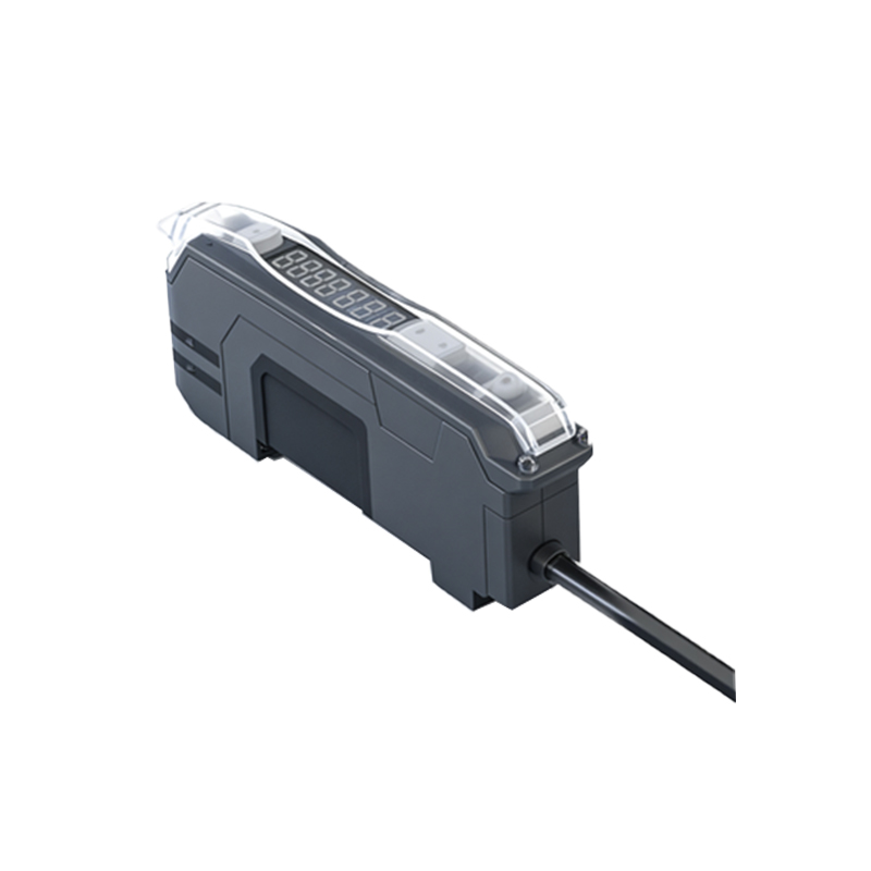
The core mechanism involves a light emitter and a receiver paired with a slotted disc or reflective tape on the rotating shaft. As the shaft rotates, the sensor generates a pulse train corresponding to each rotation. By counting pulses and comparing them to a reference, the balancer calculates the exact unbalance angle and magnitude. SATA utilizes high-gain phototransistors and modulated infrared LEDs to reject ambient light interference, ensuring stable readings even under harsh workshop conditions.
Key Technical Specifications and Performance Metrics
SATA photoelectric sensors typically operate at a supply voltage of 10-30V DC, with an output frequency up to 10 kHz. The sensing distance ranges from 10 mm to 30 mm, depending on the reflector type. Response time is less than 1 ms, crucial for high-speed rotors. The sensor housing is rated IP67, protecting against dust and water jets. These specifications allow the sensor to maintain accuracy within ±0.1 degree of phase, critical for achieving ISO 1940 balance grades.
Installation and Calibration Guidelines for Optimal Performance
Proper alignment is essential. The sensor should be mounted perpendicular to the reflective mark, with a gap of 15-20 mm. Avoid direct sunlight or strong artificial light sources. Calibration involves setting the trigger threshold via a potentiometer or software interface. SATA recommends using a non-reflective background to prevent false triggers. For dual-sensor setups, one for speed and one for phase, ensure the phase sensor is positioned at a known angle relative to the unbalance reference.
Troubleshooting Common Issues and Maintenance Tips
Common faults include erratic pulse signals due to dirty optics or misaligned reflectors. Clean the lens with isopropyl alcohol and a lint-free cloth weekly. If the sensor fails to detect, check the wiring for breaks or loose connections. Overheating can degrade the LED; ensure adequate ventilation. For intermittent errors, verify the power supply stability. SATA provides diagnostic tools that display signal strength and pulse count, aiding rapid fault isolation.
Future Trends and Advancements in SATA Balancing Sensor Technology
Emerging developments include digital photoelectric sensors with built-in microcontrollers for self-diagnostics and IoT connectivity. These sensors can communicate with PLCs via IO-Link, providing real-time data on sensor health and balancing parameters. SATA is also exploring laser-based sensors for non-contact measurement at distances exceeding 50 mm, expanding applications to large industrial fans and turbine rotors. These advancements promise even higher accuracy and reduced downtime.