Understanding the Basics of Photoelectric Sensors in Line Following
Photoelectric sensors are essential components in industrial automation for line following applications. These sensors detect the presence or absence of objects by emitting light and measuring the reflection. In line-following scenarios, they are typically used to distinguish between a reflective surface (like a white line) and a non-reflective background (like a dark floor). The key principle involves adjusting the sensitivity threshold to ensure reliable detection under varying ambient light conditions and surface textures. Engineers must consider factors such as sensor mounting height, angle, and the type of light source (infrared, visible red, or laser) to optimize performance. For robust programming, initial calibration is critical: setting the sensor’s “light-on” or “dark-on” mode based on the target line color. A common mistake is ignoring hysteresis, which can cause oscillation at line edges; incorporating a small deadband in the software logic prevents this.
Configuring Sensor Parameters for Industrial Reliability
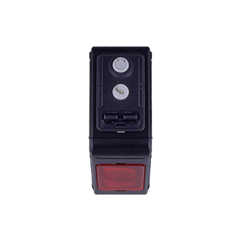
To program a photoelectric sensor for line following, start by selecting the appropriate sensor model, such as diffuse reflective or through-beam types. For line tracking, diffuse sensors are preferred due to their simplicity. In the programmable logic controller (PLC) or microcontroller code, define the sensor input as a digital signal with a debounce time of 10-20 ms to filter noise from electrical interference or mechanical vibrations. Next, establish a calibration routine: during startup, the system should read baseline values for both line and background. Use a moving average filter over 5-10 samples to smooth the data. The algorithm then compares the real-time reading against a dynamic threshold, typically set at 50% of the difference between the maximum and minimum calibration values. For multi-sensor arrays, assign each sensor a unique address and implement a voting mechanism to correct for faulty readings. Ensure the code includes error-handling routines, such as triggering an alarm if all sensors detect the same state for more than 500 ms, indicating a potential sensor failure.
Implementing PID Control for Smooth Line Tracking
For advanced line following, integrate proportional-integral-derivative (PID) control to minimize overshoot and improve path accuracy. The photoelectric sensor data serves as the feedback signal. In the control loop, define the error as the deviation from the line center, calculated from the sensor array’s weighted average position. Set the proportional gain (Kp) to adjust the immediate response, the integral gain (Ki) to eliminate steady-state error, and the derivative gain (Kd) to dampen oscillations. Typical starting values for a conveyor line are Kp=1.5, Ki=0.1, Kd=0.05, but these must be tuned empirically. Implement a slew rate limiter on the motor output to prevent abrupt acceleration. Additionally, use a state machine to transition between normal tracking, sharp turn detection, and line-lost recovery. When the line is lost, the algorithm should enter a search pattern— sweeping left and right at reduced speed—until the sensor reacquires the path.
Troubleshooting Common Programming Issues
Common issues in photoelectric sensor line-following programming include false triggers due to dust or ambient light flicker. Mitigate this by adding an optical bandpass filter in the sensor head and increasing the sensor’s response time to 2-5 ms in software. If the robot or conveyor exhibits jittery motion, reduce the PID derivative term or increase the debounce timer. For multi-sensor setups, ensure synchronization by using a common clock signal and checking for crosstalk between adjacent sensors. Another frequent problem is line drift caused by uneven floor reflectivity; implement an adaptive threshold that updates every 100 cycles using a low-pass filter with a time constant of 0.5 seconds. Finally, document the calibration sequence and parameter values in the PLC program comments for future maintenance. Testing should be conducted under worst-case conditions, such as low-lighting or high-speed operation, to validate robustness.