Understanding the Role of a Photoelectric Sensor in VFD Systems
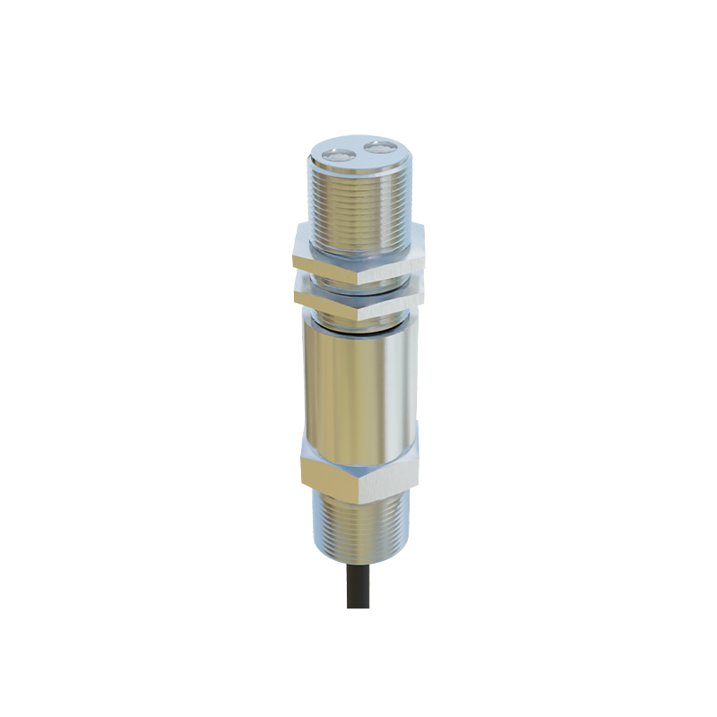
In industrial automation, a Variable Frequency Drive (VFD) is commonly used to control the speed of an AC motor by adjusting its input frequency and voltage. However, for applications requiring precise speed regulation based on real-time feedback, integrating a photoelectric sensor becomes essential. A photoelectric sensor detects the presence or position of an object without physical contact, using a light emitter and receiver. When paired with a VFD, this sensor can provide closed-loop control, adjusting motor speed dynamically based on material flow or conveyor belt position. This setup enhances efficiency, reduces energy waste, and ensures consistent product quality in manufacturing lines.
System Architecture: Connecting the Sensor to the VFD
The integration involves wiring the photoelectric sensor's output to the VFD's analog input or digital input terminals, depending on the feedback type. For example, if the sensor outputs a 0-10V DC analog signal proportional to distance, it should be connected to the VFD's analog input (e.g., AI1). Alternatively, a digital sensor can be used for simple on/off speed changes. After wiring, you must configure the VFD parameters: set the input channel (e.g., P.001 for frequency source), define the minimum and maximum frequency limits, and adjust PID control settings if required. Always verify that the sensor's supply voltage matches the VFD's auxiliary power output (typically 24V DC).
Parameter Configuration for Speed Control
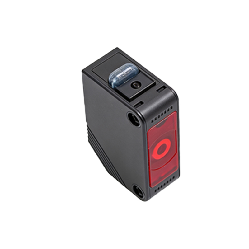
To enable sensor-based speed control, access the VFD's parameter menu. First, set the frequency reference source to an analog input (e.g., parameter 00-03 = 2 for AI1). Next, calibrate the sensor's output range to the VFD's input range using scaling parameters (e.g., P.004 = 0V corresponds to 0Hz, P.005 = 10V corresponds to 50Hz). For closed-loop applications, enable the PID function: assign PID feedback to the same analog input (e.g., P.128 = 1), set the target speed (e.g., P.129 = 1500 RPM), and adjust PID gains (P.130, P.131) for stable response. Test the system by moving an object in front of the sensor and observing the motor speed change on the VFD display.
Practical Applications and Benefits
This technology is widely used in packaging lines, conveyor systems, and material handling equipment. For instance, in a bottling plant, a photoelectric sensor detects bottle spacing and sends a signal to the VFD to adjust belt speed, preventing jams. The benefits include improved process accuracy (within 1% tolerance), reduced mechanical wear due to smoother acceleration/deceleration, and energy savings of up to 30% compared to fixed-speed operation. Additionally, it simplifies troubleshooting, as the VFD's keypad displays real-time feedback from the sensor.
Common Troubleshooting Tips
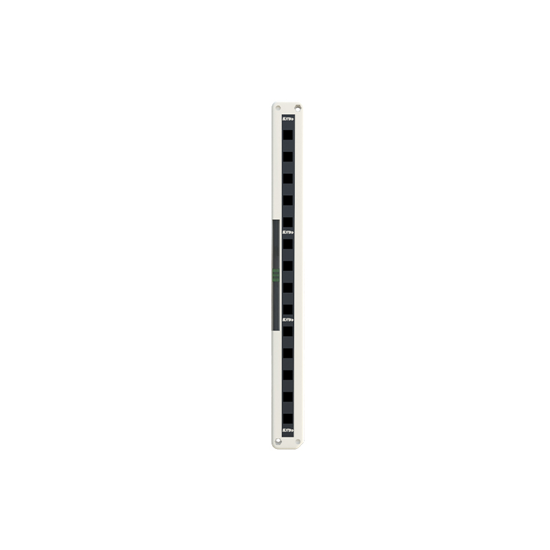
If the motor does not respond to the sensor, check the following: ensure the sensor's power LED is lit, verify wiring polarity for analog signals, and confirm the VFD's input mode (voltage vs. current). If speed fluctuates, adjust the PID filter time (e.g., P.132 = 0.1s) to dampen noise. If the sensor triggers false signals, clean the lens or increase the sensitivity threshold. Always refer to the VFD and sensor datasheets for specific parameter numbers and electrical ratings.