Introduction to Photoelectric Sensing in Motor Speed Measurement
Photoelectric sensors are widely used in industrial automation to measure the rotational speed of motors. These sensors operate based on the interruption of a light beam by a rotating component, such as a slotted disc attached to the motor shaft. The principle is simple yet highly accurate: as the disc rotates, it periodically blocks and allows light to pass, generating electrical pulses proportional to the speed. This method is non-contact, reducing wear and tear, and is ideal for harsh environments.
Key Components of the Principle Diagram
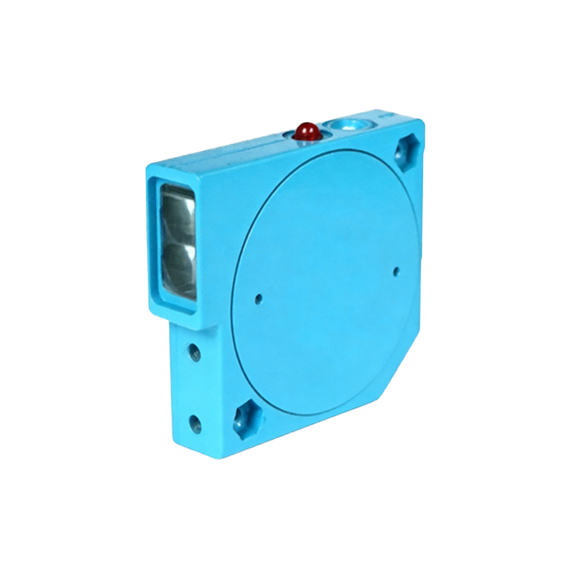
The typical principle diagram includes a photoelectric sensor (comprising a light emitter and receiver), a slotted or reflective disc mounted on the motor shaft, a power supply, and a signal processing unit. The emitter, often an LED, produces a focused beam of light. The receiver, such as a phototransistor, detects the light. The disc has slots or marks that create alternating light and dark intervals. The diagram also shows connections to a microcontroller or counter for pulse counting.
How the Sensor Generates Speed Signals
When the motor rotates, the disc’s slots pass through the light beam. Each slot allows light to reach the receiver, generating a high signal. When a solid part of the disc blocks the beam, the output goes low. This creates a train of square wave pulses. The frequency of these pulses is directly proportional to the motor’s rotational speed. For example, if the disc has N slots, one complete revolution produces N pulses. The speed in RPM (revolutions per minute) is calculated by dividing the pulse frequency by N and multiplying by 60.
Practical Circuit Implementation
In the circuit diagram, the phototransistor’s collector is connected to a pull-up resistor and a DC voltage source, while the emitter is grounded. The output is fed into a comparator or Schmitt trigger to clean the signal, ensuring stable digital pulses. A capacitor is often added to filter noise from the motor’s electromagnetic interference. The cleaned pulses are then sent to a frequency counter or a microcontroller’s input pin for real-time speed monitoring.
Advantages and Considerations
Photoelectric sensors offer high resolution and fast response, making them suitable for precise speed control in applications like conveyor belts, robotics, and CNC machines. However, factors such as dust, vibration, and ambient light can affect accuracy. Engineers must choose appropriate sensor types (through-beam, retro-reflective, or diffuse) and disc materials (metal or plastic) based on the environment. The principle diagram should include protective components like transient suppressors to enhance reliability.
Calculating Motor Speed from Sensor Data
To calculate speed, the number of pulses per second (frequency) is measured. For a disc with 60 slots, a frequency of 60 Hz corresponds to 60 RPM. Engineers often use a formula: RPM = (Frequency × 60) / Number of slots. This calculation is straightforward with a microcontroller, which can also store historical data for trend analysis. The diagram should illustrate the signal path from sensor to processor, emphasizing the conversion from optical to electrical impulses.
结束。