Understanding the Basics of EPC Photoelectric Sensor Indicators
In industrial automation, EPC photoelectric sensors are critical for object detection, positioning, and counting. The indicator lights on these sensors provide real-time diagnostic information. Typically, a green LED signifies normal operation and stable power supply, while a yellow or orange LED indicates the sensor is detecting an object. A flashing or red light often signals alignment issues, contamination on the lens, or a fault in the output circuit. Engineers must familiarize themselves with these color codes to minimize downtime.
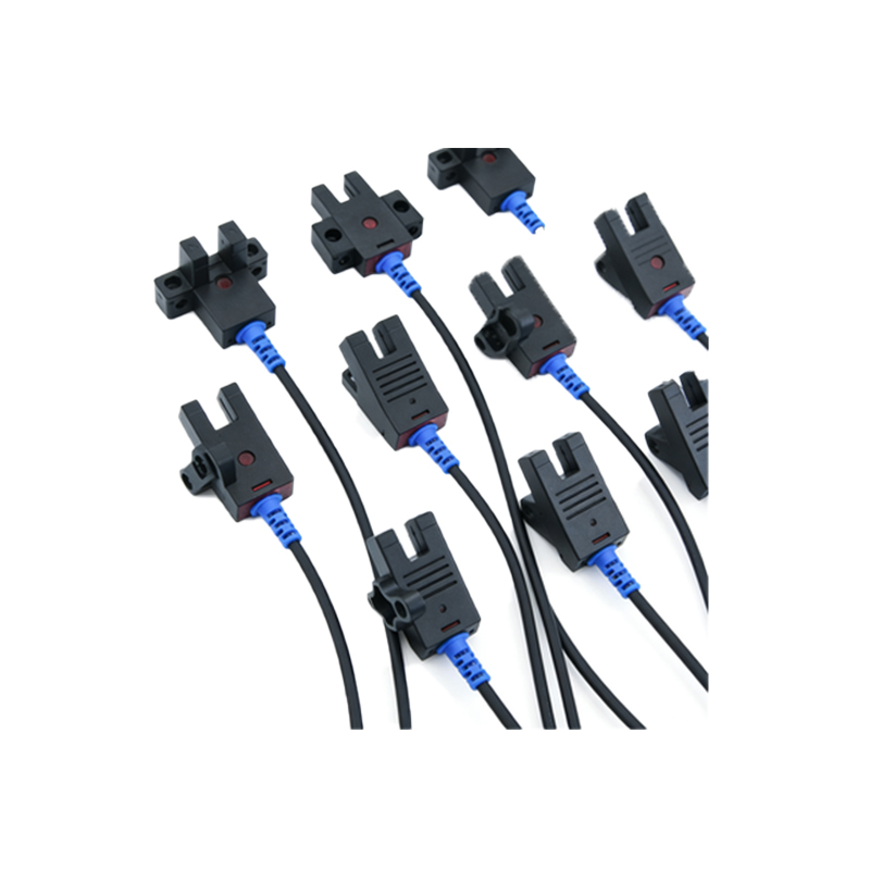
Common Indicator Light Patterns and Their Meanings
When the sensor is idle, a steady green light means the device is powered and ready. During active detection, the output indicator (usually yellow) turns solid when a target is within range. If the yellow light blinks rapidly, it may suggest marginal sensing conditions, such as a reflective object at the edge of the detection zone. A red light often indicates a short circuit, overload, or internal error. For example, on the EPC series, a double-flash red pattern typically points to a lens contamination issue.
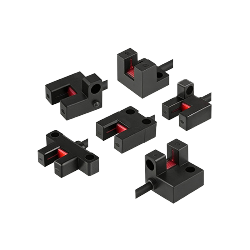
Troubleshooting with Indicator Lights
Use the indicator lights as a first-line diagnostic tool. If the green power light is off, check the power supply voltage and connections. If the output light (yellow) remains off despite a target present, verify the sensor’s alignment and sensitivity settings. For a flashing red light, inspect the sensor lens for dust, oil, or moisture. Cleaning with a soft, lint-free cloth often resolves the issue. If the problem persists, consult the sensor’s datasheet for specific error codes.
Best Practices for Sensor Installation and Maintenance
To ensure reliable indicator light performance, install the sensor at the recommended distance from the target and avoid direct exposure to strong ambient light sources, which can cause false readings. Regularly check the indicator status during preventive maintenance. For harsh environments, use sensors with a high ingress protection (IP) rating, such as IP67, to prevent contamination. Document any unusual light patterns for future reference.
Advanced Diagnostic Features in Modern EPC Sensors
Newer EPC models incorporate multi-color LEDs that can display various states, such as blue for teach-in mode or magenta for a warning about low margin. Some sensors offer a diagnostic output that pulses the indicator in a specific sequence to pinpoint issues like excessive background interference. Engineers should study the user manual to fully leverage these features for efficient troubleshooting.