Introduction to Photoelectric Sensors
Photoelectric sensors are critical components in industrial automation, utilizing light to detect the presence, absence, or distance of objects. These devices operate on the principle of emitting a light beam (typically infrared or visible) and measuring changes in the received signal. Engineers rely on them for precise positioning, sorting, and safety applications. This guide explores a series of experiment videos that demonstrate key principles, setups, and troubleshooting techniques, serving as a practical resource for both novice and experienced professionals.
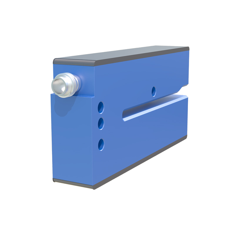
Fundamental Experiment: Through-beam Sensor Setup
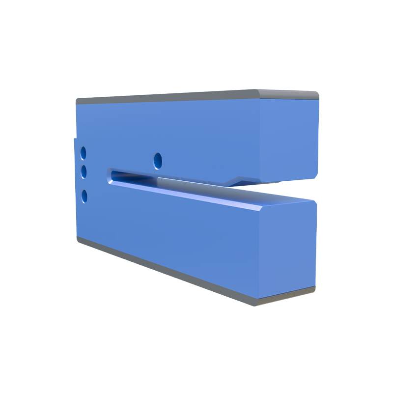
The through-beam sensor consists of a separate emitter and receiver. In this experiment, the emitter sends a continuous light beam to the receiver. When an object interrupts the beam, the output signal changes. The video demonstrates proper alignment using mounting brackets and laser aids, highlighting the importance of stable mounting to avoid false triggers. Key parameters such as sensing range (up to 30 meters) and response time (below 1 ms) are measured with an oscilloscope. This setup is ideal for long-distance detection in conveyor systems.
Reflective Sensor Calibration Experiment
Reflective sensors combine emitter and receiver in one housing, detecting objects by sensing reflected light. The video shows calibration steps: adjusting the sensitivity potentiometer to avoid background interference. A test with a matte black object versus a shiny metal surface illustrates the impact of reflectivity. Engineers learn to set a margin of safety by using a teach-in function, which stores the ambient light level. This experiment is crucial for applications like packaging line object counting.
Background Suppression Experiment
Background suppression sensors use a triangulation principle to ignore objects beyond a set distance. The experiment video demonstrates setting the cutoff distance using a sliding adjustment. A white target at 100 mm is detected, while a black target at 150 mm is ignored. The video shows real-time output on a PLC input module, emphasizing the importance of background color and angle. This technology is widely used in robotic pick-and-place systems to avoid false detections from floors or walls.
Fiber Optic Sensor Testing
Fiber optic sensors extend the reach of photoelectric detection into tight spaces and harsh environments. The experiment uses a fiber optic amplifier connected to a threaded lens. The video shows how to bend the fiber cable at a 90-degree angle without significant signal loss. Sensitivity is tested with a 0.5 mm diameter wire, demonstrating the sensor's ability to detect small parts. This setup is essential for microelectronics assembly lines.
Troubleshooting Common Issues
This video addresses typical field failures: crosstalk between adjacent sensors, lens contamination, and ambient light saturation. The expert demonstrates using a shield tube for crosstalk reduction and cleaning with isopropyl alcohol. A test with a fluorescent lamp shows how to filter out interference using a modulated light source. Engineers learn to use a multimeter to verify power supply stability and check output transistor states. These practical tips reduce downtime in automated factories.
Advanced Integration with PLC and HMI
The final video covers integrating a photoelectric sensor into a Programmable Logic Controller (PLC) system using a 24V DC interface. The HMI screen displays count values and alarm states. The experiment uses a Siemens S7-1200 PLC with a high-speed counter module for fast triggering. Engineers see how to map sensor outputs to ladder logic for sorting and rejecting defective parts. This integration demonstrates the sensor's role in Industry 4.0 data collection.