Introduction to Groove Photoelectric Sensors
Groove photoelectric sensors, also known as fork or U-shaped sensors, are critical components in industrial automation for non-contact object detection. They consist of a transmitter and receiver housed in a single unit, creating a reliable sensing gap. Among various wiring configurations, the pink wire output has gained attention for its specific signaling capabilities, often indicating a dedicated alarm or fault condition. This article explores the technical aspects, wiring standards, and practical applications of groove photoelectric sensors equipped with a pink output wire, providing insights for electrical engineers and maintenance professionals.
Technical Specifications and Pink Wire Function
A typical groove photoelectric sensor with a pink wire output operates on a DC power supply, commonly 10-30V DC. The standard wiring includes brown (power +), blue (power -), black (normally open output), white (normally closed output), and pink (alarm or diagnostic output). The pink wire, per industry norms like IEC 60947-5-2, is designated for a self-diagnostic or status indication output. This output remains low (0V or open collector) during normal operation and switches to a high state (Vcc) when the sensor detects internal faults, such as emitter degradation, lens contamination, or excessive temperature. Engineers must verify the sensor datasheet to confirm polarity and load requirements, as the pink wire typically sinks or sources up to 100 mA.
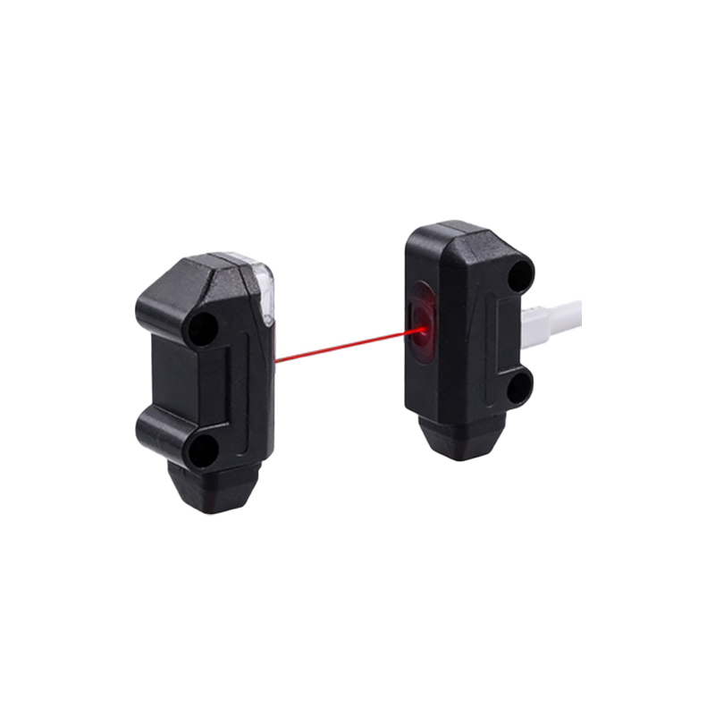
Wiring and Integration in Control Systems
Integrating a groove photoelectric sensor with a pink wire output requires careful consideration of the control system architecture. For example, in a programmable logic controller (PLC) setup, the pink wire can be connected to a dedicated digital input module to trigger an alarm routine. Ensure the pink output is pulled up to Vcc via a resistor if the sensor has an open-collector configuration. Ground the blue wire to the common negative, and connect the brown wire to a stable DC source. The black and white wires handle standard sensing outputs (N.O. and N.C.), while the pink wire provides a separate diagnostic channel. Use shielded cables for long distances to mitigate electromagnetic interference, especially in noisy industrial environments with motors or inverters.
Common Applications and Troubleshooting Tips
These sensors are ideal for conveyor systems, packaging machinery, and material handling, where continuous monitoring is critical. The pink wire output serves as a pre-failure warning, allowing predictive maintenance. For instance, on a bottle-filling line, a groove sensor detects caps; if the pink wire signals an alarm, operators can clean the sensor lens before downtime occurs. Troubleshooting common issues: if the pink wire remains high constantly, check for power supply fluctuations or a damaged emitter. If it fails to activate during faults, verify the load current does not exceed the sensor’s rating. Use a multimeter to measure voltage between brown and blue (should be 10-30V DC) and between pink and blue during alarm conditions (should match Vcc).
Benefits and Industry Standards Compliance
Adopting sensors with pink wire outputs enhances system reliability by providing early fault detection, reducing unplanned downtime. They comply with international standards such as IEC 60947-5-2 for proximity switches, ensuring interoperability. Additional benefits include simplified diagnostics without extra external sensors and reduced wiring complexity in multi-sensor arrays. For electrical engineers, this feature supports Industry 4.0 initiatives by enabling condition monitoring data to be integrated into SCADA systems. Always refer to the manufacturer’s wiring diagram, as pin assignments may vary by brand (e.g., Omron, Banner, or Sick). Properly terminating the pink wire with a ferrule or crimp connector ensures a stable connection in high-vibration environments.
Conclusion: Optimizing Performance with Pink Wire Output
Mastering the use of groove photoelectric sensors with pink wire outputs empowers engineers to build more intelligent and resilient automation systems. By understanding the technical wiring, applying correct integration methods, and leveraging the diagnostic output for predictive maintenance, industrial operations can achieve higher efficiency and lower maintenance costs. As sensor technology evolves, the pink wire remains a valuable tool for real-time health monitoring in harsh industrial settings.