Understanding UV Photoelectric Sensors
UV photoelectric sensors are specialized devices that use ultraviolet light to detect objects, materials, or surface characteristics. Unlike standard infrared sensors, they offer higher precision for applications like glass edge detection, semiconductor wafer alignment, and UV ink marking. Their wiring diagram varies based on sensor type—through-beam, retroreflective, or diffuse—and output configuration (NPN or PNP). Always consult the datasheet for pin assignments, as incorrect wiring can damage the sensor or lead to false readings.
Standard Wiring Color Codes and Pinout
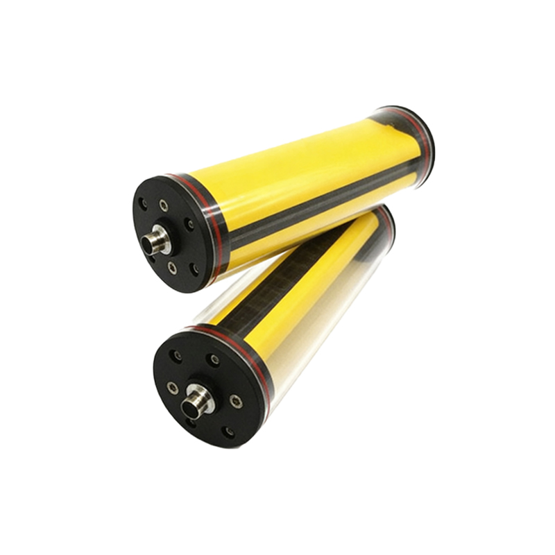
For most industrial UV sensors, the wire colors follow a consistent standard: brown for power supply (usually 10-30V DC), blue for ground (0V), and black for output signal. Some models include a white wire for remote test or selectable logic. For example, a 4-wire UV sensor might have: brown (V+), blue (V-), black (NO output), and white (NC output). In hazardous environments, check for intrinsically safe versions with distinct color coding (e.g., green for shield). Always use a multimeter to verify voltage levels before connecting.
Wiring a UV Through-Beam Sensor Pair

Through-beam UV sensors consist of a separate emitter and receiver. Connect the emitter: brown to 24V DC, blue to ground. For the receiver, wire brown to 24V, blue to ground, and black to the PLC input. If using a PNP configuration, the output will be high when the beam is unbroken; for NPN, it will sink to ground. Add a 1kΩ pull-up resistor on the receiver’s output if the PLC input requires a voltage signal. Test alignment using a UV test card, as UV light is invisible to the human eye.
Integrating a Retroreflective UV Sensor
Retroreflective UV sensors combine emitter and receiver in one housing, requiring a reflector. Wire the brown wire to 24V, blue to ground, and black to the controller input. For sensors with adjustable sensitivity, connect the white wire to a potentiometer or digital input for threshold setting. Ensure the reflector is placed at a 90° angle relative to the sensor axis. In dusty environments, use an air purge or protective tube to maintain signal integrity.
Connecting a Diffuse UV Sensor with Background Suppression
Diffuse UV sensors detect targets by reflected UV light. Wire as: brown (24V), blue (ground), black (output). Some models have an additional blue/green wire for analog output (e.g., 0-10V or 4-20mA). For background suppression, connect the white wire to a teach-in button or PLC output to set the cutoff distance. Verify the sensing range using a UV-reflective target (e.g., PTFE tape) since standard surfaces may absorb UV.
Troubleshooting Common Wiring Issues
Common errors include reversed polarity (brown/blue swapped) causing no output; loose connections leading to intermittent faults; and incorrect load type (e.g., connecting a PNP output to an NPN input). Use a UV flashlight to simulate the sensor beam during testing. If the sensor fails to switch, measure voltage between brown and blue (should be 24V ±10%). For noise issues, add a ferrite bead on the power line or use shielded cables, connecting the drain wire to earth ground.