Understanding Photoelectric Sensor Delay Types
In industrial automation, photoelectric sensors often require delay adjustments to optimize performance in specific applications. The two primary delay types are ON-delay (delay on make) and OFF-delay (delay on break). ON-delay means the sensor output activates only after a preset time after the target is detected; OFF-delay holds the output active for a set duration after the target leaves the detection zone. Understanding this distinction is crucial for selecting the correct adjustment method.
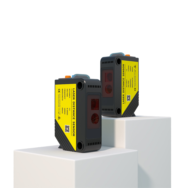
Tools and Safety Precautions
Before adjusting, ensure the sensor is powered down or isolated from the control circuit to prevent accidental machine startup. You will need a small flathead screwdriver (for potentiometer adjustments) and a timer or oscilloscope (for verifying delay settings). Consult the sensor datasheet for maximum delay ranges—typically 0.1 to 10 seconds for standard models. Always follow lockout/tagout procedures if the sensor is part of a live system.
Step-by-Step Adjustment Procedure for Potentiometer-Based Sensors
1. Locate the delay adjustment potentiometer on the sensor housing. It is often marked with symbols like "DELAY" or "TIME."
2. Use the screwdriver to turn the potentiometer clockwise to increase delay time, or counterclockwise to decrease it. For precise settings, mark the initial position.
3. Power the sensor and simulate a target passing through the detection beam. Observe the output signal with a multimeter or PLC input indicator.
4. Fine-tune the potentiometer until the output activates or deactivates at the desired delay interval. For example, for an OFF-delay of 500ms, adjust until the output remains high for exactly 500ms after the target leaves.
Digital Programming Methods for Smart Sensors
Modern photoelectric sensors with digital interfaces (e.g., IO-Link, teach-in buttons) allow parametric delay adjustments via software or push-button sequences. Access the sensor's configuration menu using a manufacturer-specific tool (e.g., SICK SOPAS, ifm moneo). Navigate to "Timers" or "Delay Settings" and input the desired time value in milliseconds or seconds. Save the configuration and verify with a test object. This method eliminates mechanical wear and offers repeatability to ±1%.
Common Troubleshooting Tips
If the delay does not function as expected, check for dirty optics or misalignment causing false triggers. Verify that the sensor's output type (PNP/NPN) matches the load. For very short delays (<10ms), ensure the power supply has low ripple. In noisy environments, shield cables and use ferrite cores. If using a potentiometer, confirm it is not at the end of its travel (audible clicks indicate limit).
Application-Specific Delay Recommendations
For conveyor belt counting, use a 100-300ms OFF-delay to avoid double-counting items. For part detection in fast pick-and-place robots, set ON-delay to 5-10ms to filter out debris. In liquid level sensing, a 500ms ON-delay prevents false signals from splashes. Always test the delay under real operating conditions and adjust for environmental factors like vibration or ambient light.
Final Verification and Maintenance
After adjustment, run a full cycle of the machine to confirm stable operation. Record the delay setting in the sensor's maintenance log. Recheck calibration every 6 months, as potentiometers may drift due to thermal cycling. For critical applications, consider sensors with digital delay memory to retain settings after power loss.