Understanding the Basics of Photoelectric Sensors and 24V Systems
Photoelectric sensors are essential components in industrial automation, used for detecting objects, distances, and positions without physical contact. They typically operate on low-voltage DC power, with 24V DC being the most common standard in modern control systems. Before connecting, verify the sensor's datasheet: most photoelectric sensors accept 10-30V DC, making 24V a safe and efficient choice. Ensure your power supply is regulated and can provide sufficient current (usually 50-200 mA per sensor). Always use a dedicated power source or a protected branch from a PLC power supply to avoid noise interference.
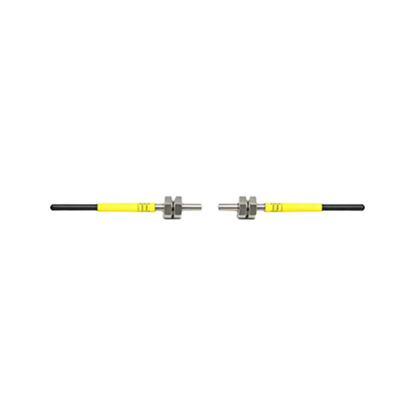
Wiring the Power Connections: Step-by-Step Instructions
Begin by identifying the sensor's power pins. Standard color codes for 24V DC sensors: brown wire for +24V (positive), blue wire for 0V (negative/ground). Connect the brown wire to the positive terminal of your 24V DC power supply. Connect the blue wire to the negative terminal (common ground). For sensors with separate load wires (e.g., black or white for output), do not connect them to power directly. Use a multimeter to confirm voltage at the sensor terminals before powering up. If using a switch-mode power supply, ensure proper grounding to avoid floating voltages.
Integrating the Sensor Output with a PLC or Controller
The output of a photoelectric sensor is typically NPN (sinking) or PNP (sourcing). For 24V systems, PNP sensors are more common in North America, while NPN is prevalent in Asia. With a PNP sensor, the output wire (often black) will switch +24V when activated. Connect this to a digital input on your PLC that is configured for sinking (usually a 24V input module). For NPN sensors, the output sinks to 0V; connect to a sourcing input module. Always include a current-limiting resistor (e.g., 1kΩ) in series if the sensor does not have built-in short-circuit protection. Test with a load (e.g., a relay or LED) before permanent connection.
Troubleshooting Common Connection Issues
If the sensor fails to power on, check for reversed polarity (damage may occur). Use a voltmeter to measure between brown and blue: should read 24V DC ±10%. If the output does not switch, verify the target object is within the sensing range and that the sensor's sensitivity is adjusted (potentiometer on some models). Noise issues (false triggers) often stem from long cable runs (over 10 meters) without shielded cable. For inductive loads (relays, solenoids), always add a flyback diode across the load to protect the sensor output. Ensure the power supply's ground is shared with the PLC ground to prevent potential differences.
Best Practices for Reliable Long-Term Operation
Use twisted-pair shielded cable for sensor wiring, especially in high-EMI environments. Keep sensor cables separate from high-voltage AC lines (minimum 15 cm distance). Install a fuse (e.g., 0.5A fast-blow) on the +24V line to protect against short circuits. For outdoor or wet applications, use sensors with IP67 rating and seal connections with silicone or heat-shrink tubing. Regularly inspect connections for corrosion or loosening. Label all wires clearly for maintenance. If using multiple sensors, calculate total current draw to avoid overloading the power supply (typical limit: 80% of rated capacity).