Understanding Diffuse Reflective Photoelectric Sensors
In industrial automation, diffuse reflective photoelectric sensors are essential for non-contact object detection, especially in applications where a separate reflector or receiver is impractical. Unlike through-beam or retro-reflective sensors, a diffuse sensor emits a light beam (typically infrared, red, or laser) and detects the light reflected directly from the target object. The sensor’s receiver is integrated into the same housing, making it a compact and cost-effective solution for detecting objects with varying surface properties. For engineers, the key advantage lies in its simplicity and ability to detect objects over short to medium ranges, typically from a few centimeters up to several meters, depending on the model and background suppression technology used.
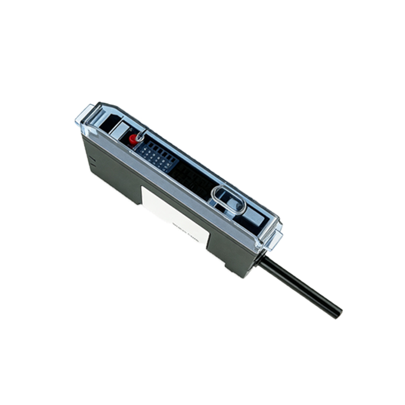
Key Performance Metrics for Industrial Applications
When specifying a high-quality diffuse reflective sensor, engineers must evaluate several critical parameters. First, the sensing range is not a fixed value; it depends on the target’s reflectivity. A sensor rated for 1 meter on a white card may only achieve 0.3 meters on a dark, matte object. Second, background suppression is vital for preventing false triggers from shiny floors or conveyor belts. Advanced sensors use triangulation or time-of-flight (ToF) principles to accurately ignore background surfaces. Third, response time (e.g., 0.5 ms to 5 ms) affects high-speed counting and sorting applications. Finally, environmental ratings such as IP67 or IP69K ensure reliability in dusty, wet, or washdown environments common in food processing or automotive lines.
Selecting the Right Sensing Technology: Infrared vs. Red Light vs. Laser
The choice of light source directly impacts sensor performance. Infrared (IR) sensors are cost-effective and ideal for general-purpose detection of opaque objects, but they struggle with highly reflective or transparent materials. Red light (visible red LED) sensors offer better alignment visibility and improved performance on reflective or colored targets, making them popular in packaging and logistics. Laser sensors provide the longest range and smallest spot size, enabling precise detection of small components (e.g., screw threads) or objects in narrow gaps. For engineers, matching the light source to the target’s color, texture, and material is crucial to minimize false readings and maximize repeatability.
Installation and Calibration Best Practices
Proper installation is critical for achieving reliable performance. First, ensure the sensor’s optical axis is perpendicular to the target surface, as angular misalignment reduces effective range. Second, adjust the sensitivity potentiometer (or teach-in function) using a representative sample of the actual target, not a standard test card. For sensors with background suppression, perform a “teach” process on the background surface first, then on the target. Third, consider electrical noise: use shielded cables and avoid running sensor wires parallel to high-power motor cables. Finally, test the sensor under worst-case conditions, such as low ambient light or high dust levels, to verify stability.
Common Failure Modes and Troubleshooting
Even high-quality sensors can fail in harsh industrial environments. One frequent issue is optical contamination: dust, oil, or condensation on the lens can drastically reduce sensing range. Regular cleaning with a lint-free cloth and isopropyl alcohol is recommended. Another problem is crosstalk when multiple sensors are mounted close together. Solutions include using sensors with different modulation frequencies or adding mechanical barriers. If the sensor consistently fails to detect dark or irregularly shaped objects, consider switching to a model with a more powerful emitter or a specialized “black object” algorithm. Always verify power supply voltage (e.g., 10-30 VDC) and ripple, as undervoltage can cause erratic behavior.
Future Trends: Smart Sensors and Industry 4.0 Integration
The latest diffuse reflective sensors are evolving into intelligent devices with IO-Link communication. This digital interface allows engineers to remotely configure parameters, monitor signal strength, and receive predictive maintenance alerts. For example, a sensor with IO-Link can report a gradual drop in signal intensity due to lens contamination before a failure occurs. Additionally, multi-point detection sensors can now differentiate between multiple targets in a single beam path, enabling more complex automation tasks. For engineers planning long-term system upgrades, investing in sensors with Industry 4.0 capabilities reduces downtime and simplifies integration with PLCs and SCADA systems.