Introduction to Photoelectric Sensor Disk Technology
Photoelectric sensors are critical components in industrial automation, providing reliable detection of objects without physical contact. The sensor disk, a rotary encoder element, plays a key role in converting mechanical motion into electrical signals. In this video guide, we explore the working principles, components, and applications of photoelectric sensor disks, designed for electrical engineers and technicians seeking practical knowledge.
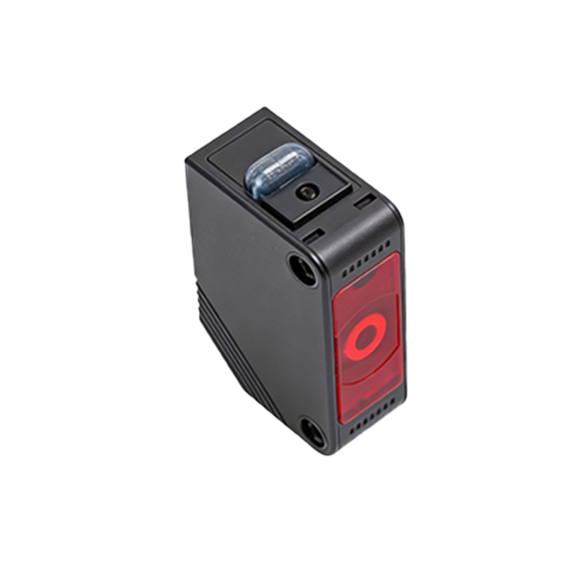
How a Photoelectric Sensor Disk Works
The sensor disk consists of a rotating disc with alternating transparent and opaque segments, typically made of metal or plastic. A light source, such as an LED, emits a beam onto the disk, while a photodetector (e.g., a photodiode) receives the transmitted or reflected light. As the disk rotates, the pattern interrupts the light beam, generating a series of pulses. These pulses correspond to specific rotational positions or speeds, enabling precise feedback in motor control and positioning systems.

Key Components of the Sensor Disk System
The system includes three main parts: the emitter, the receiver, and the disk itself. The emitter, usually an infrared or visible LED, provides a stable light source. The receiver, a phototransistor or photodiode, detects light changes and converts them into electrical signals. The disk’s pattern, often with incremental or absolute encoding, determines the resolution. For example, a disk with 1000 slots offers 1000 pulses per revolution, achieving high precision in applications like conveyor belts or robotic arms.
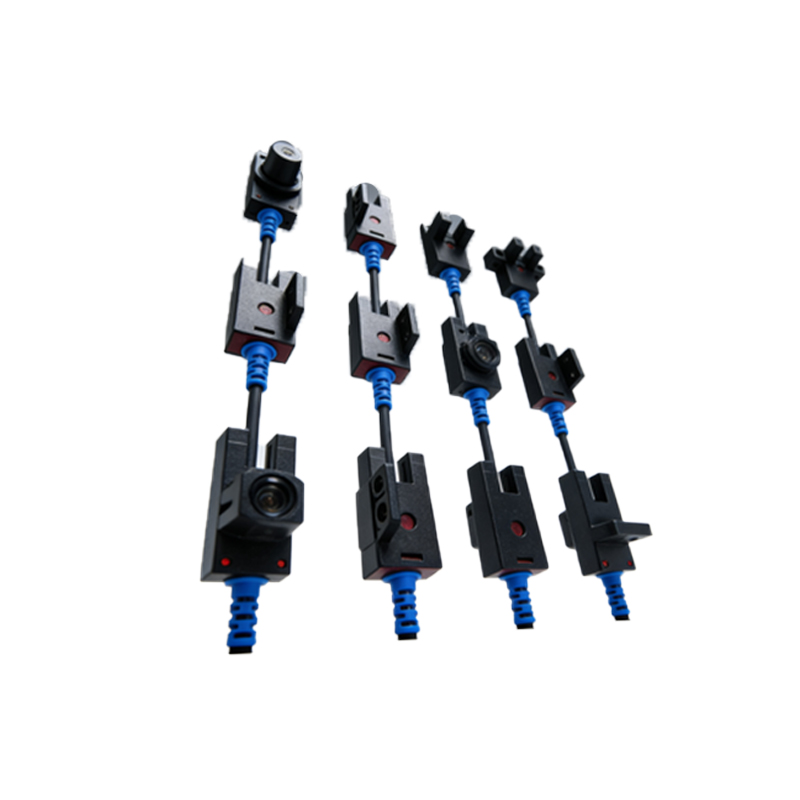
Types of Photoelectric Sensor Disks
Two common types are through-beam and reflective sensor disks. Through-beam designs use a separate emitter and receiver on opposite sides of the disk, offering high accuracy but requiring alignment. Reflective designs combine emitter and receiver on the same side, using a reflective surface on the disk to detect rotation. Engineers often choose through-beam for dusty environments and reflective for compact setups, balancing cost and performance.
Applications in Industrial Automation
Photoelectric sensor disks are widely used in CNC machines, elevators, and packaging equipment. They provide real-time feedback for speed control, position tracking, and direction detection. For instance, in a conveyor system, the disk helps maintain consistent motor speed, improving efficiency and reducing wear. The video demonstrates how to integrate these sensors with PLCs, using common wiring and signal processing techniques.
Troubleshooting and Calibration Tips
Common issues include misalignment, dust accumulation, or signal noise. To troubleshoot, check the disk’s cleanliness and ensure the emitter-receiver pair is properly aligned. Use an oscilloscope to monitor pulse waveforms for irregularities. Calibration involves adjusting the threshold voltage of the photodetector to avoid false triggers. The video shows step-by-step procedures for field adjustments, emphasizing safety practices like disconnecting power before maintenance.
Conclusion and Further Learning
Mastering photoelectric sensor disk principles enhances your ability to design robust automation systems. For deeper understanding, explore incremental and absolute encoding techniques, or experiment with different disk patterns. The accompanying video provides hands-on demonstrations, including wiring diagrams and real-world examples. We recommend reviewing datasheets from manufacturers like Omron or Sick for specific models.