Understanding Bowei Jingke Photoelectric Sensors
Bowei Jingke photoelectric sensors are essential components in industrial automation, used for detecting objects, distance, or presence without physical contact. These sensors operate using light beams, typically infrared or visible red light, to trigger output signals. As an electrical engineer, proper wiring is critical to ensure reliable performance. Common models include through-beam, retro-reflective, and diffuse reflection types. Before wiring, verify the sensor’s specifications: power supply voltage (e.g., 10-30V DC), output type (NPN or PNP), and cable length. Always consult the datasheet for pin assignments and environmental ratings.
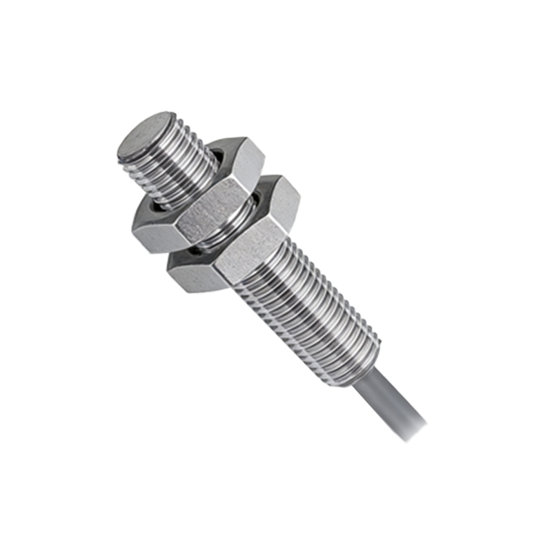
Essential Tools and Safety Precautions
Start by gathering the right tools: a multimeter, wire strippers, screwdrivers, and heat-shrink tubing. Safety is paramount. Disconnect power before handling wires. Wear insulated gloves and use a grounding strap to avoid electrostatic discharge (ESD) damage. Confirm the sensor’s power source matches your system (e.g., 24V DC). Check for short circuits with a multimeter. Label all wires to avoid confusion, especially in complex cabinets. For outdoor installations, use weatherproof connectors and cable glands rated for IP67.
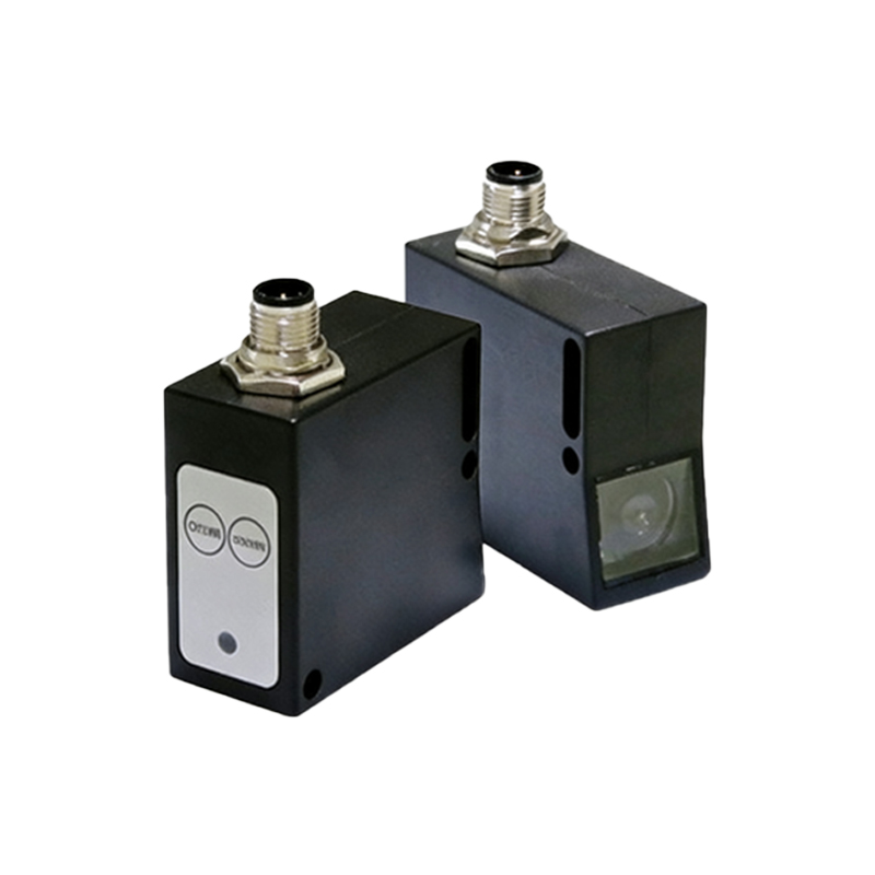
Wiring Steps for NPN and PNP Outputs
Bowei Jingke sensors typically have three wires: brown (positive), blue (negative), and black (output). For an NPN configuration, connect brown to the positive terminal of the power supply (e.g., +24V), blue to the common ground (0V), and black to the load’s negative side. The load’s positive side ties to the power supply. This creates a sinking output, ideal for PLC input modules with common positive. For PNP, connect brown to +24V, blue to 0V, and black to the load’s positive side. The load’s negative side goes to ground. This provides a sourcing output, common for PLCs with common negative. Use a pull-up or pull-down resistor if needed. Test continuity with a multimeter before powering up.
Common Wiring Mistakes and Fixes
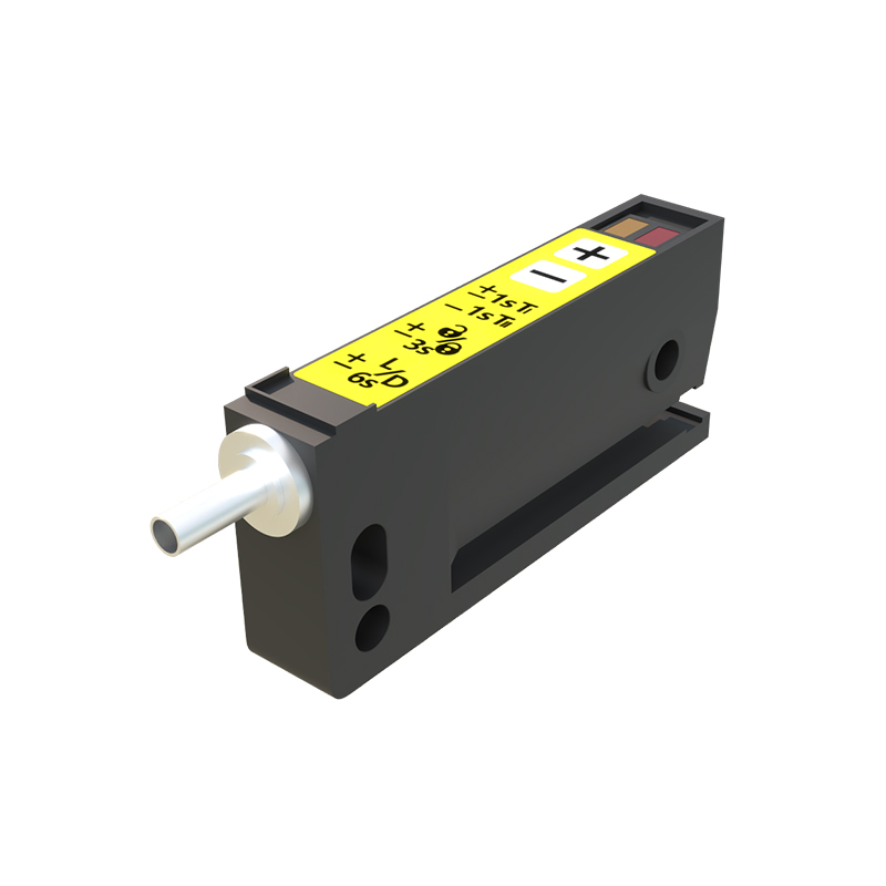
Mistakes can lead to sensor failure or system downtime. One common error is reversing power polarity: brown to ground and blue to positive. This can damage the sensor. Always double-check the datasheet. Another issue is mismatched output types. For example, connecting a PNP sensor to an NPN PLC input requires a relay or converter. Avoid loose connections by using ferrules or soldered joints. Ensure cable shielding is grounded at one end only to prevent ground loops. If the sensor triggers erratically, inspect for voltage drops or electromagnetic interference (EMI). Use twisted-pair cables for long runs (over 10 meters).
Testing and Troubleshooting After Wiring
After wiring, power up the system. Use a multimeter to measure voltage across the brown and blue wires (should match the rated supply). Then, test the output: for NPN, the black wire should show 0V when active; for PNP, it should show supply voltage. If no response, check the load alignment or sensitivity. For retro-reflective sensors, clean the reflector surface. Use a laser alignment tool for through-beam pairs. If the sensor still fails, inspect for internal damage or moisture ingress. Replace faulty units promptly. Document all wiring for future maintenance.
Advanced Integration Tips for Industrial Systems
For complex systems, wire Bowei Jingke sensors to a programmable logic controller (PLC) using terminal blocks. Use shielded cables to reduce noise, especially near motors or drives. Configure the PLC input as sinking (for NPN) or sourcing (for PNP). Implement debounce timers in software to filter false triggers. For analog output sensors, connect the white or gray wire to an analog input module. Calibrate using a potentiometer if available. Consider redundant wiring for critical applications, such as two sensors in series. Always follow local electrical codes (e.g., NEC or IEC).