Understanding Photoelectric Sensor Fundamentals
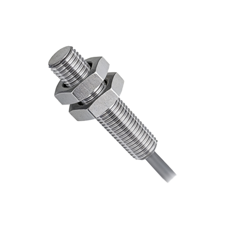
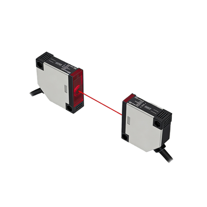
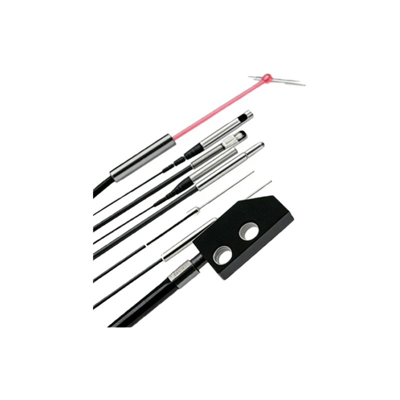
Photoelectric sensors are essential components in industrial automation, detecting objects using light beams. Before drawing their schematic in CAD, engineers must grasp the basic principle: a transmitter emits light, and a receiver detects changes in light intensity caused by an object's presence. Common types include through-beam, retroreflective, and diffuse sensors. For CAD drawing, focus on the sensor's block diagram: a power supply (typically 10-30V DC), an output stage (NPN or PNP), and a sensing element (LED and phototransistor).
Setting Up Your CAD Environment for Sensor Drawings
Open your CAD software (e.g., AutoCAD or DraftSight) and create a new drawing with the following settings: units in millimeters (mm), grid snap on, and layer management. Create dedicated layers for power, signal, and outline paths. Use color coding: red for power lines, blue for output signals, and black for enclosure outlines. Set the text style to a standard font like Arial or Isocpeur for clarity. Ensure the drawing template includes a title block with revision notes, as electrical schematics often require traceability.
Drawing the Photoelectric Sensor Block Diagram
Start with the sensor's main block. Use the RECTANGLE command to create a 50x30 mm rectangle representing the sensor housing. Inside, draw two circles (diameter 10 mm) for the LED transmitter and phototransistor receiver, spaced 15 mm apart. Label these as 'Tx' and 'Rx' using the TEXT command. Add power pins: a positive terminal (+V) on the left side and a ground terminal (GND) on the bottom. Use LINEs with a 0.5 mm lineweight for clarity. For the output, draw a square (5x5 mm) at the top right corner, labeled 'Output'.
Adding Electrical Connections and Wiring Details
Connect the power supply to the sensor block. Draw a vertical line from the +V pin to a 24V DC symbol (a small circle with a plus sign), and a line from GND to a ground symbol (three decreasing horizontal lines). For the output, draw a line from the Output node to a load symbol (a resistor icon, R). Use the POLYLINE function to create a clean path. Add wire labels like '24Vdc', '0V', and 'Signal Out' using the MTEXT command. Ensure all connections are orthogonal (using ORTHO mode) for professional appearance.
Including Wiring Diagram for NPN and PNP Configurations
Photoelectric sensors often have NPN (sinking) or PNP (sourcing) outputs. Draw two separate sections below the main block. For NPN: connect the Output to the collector of an NPN transistor symbol (arrow pointing inward). For PNP: connect to the emitter of a PNP transistor (arrow pointing outward). Use the CIRCLE and LINE commands to create transistor symbols. Add a 1kΩ pull-up resistor for NPN or pull-down resistor for PNP, drawn as a zigzag line using the POLYLINE method. Label each configuration clearly.
Finalizing the Schematic with Annotations and Standards
Complete the drawing by adding reference designators (e.g., 'U1' for the sensor, 'R1' for resistors). Use the TABLE command to create a parts list at the bottom right, including part numbers like 'E3F-5DN1'. Add a title block with project name, date, and revision number. For compliance with IEC 60617 or IEEE standards, ensure symbols match standard libraries. Finally, run a consistency check: verify all connections are unbroken and no overlapping lines exist. Save the file as a .DWG format and export a PDF for documentation.