1. Understanding Photoelectric Sensor Basics for CAD Modeling
As an electrical engineer, you know that photoelectric sensors are critical in automation for detecting objects without physical contact. Before diving into CAD, define the sensor type — through-beam, retro-reflective, or diffuse. Each has distinct optical paths and housing shapes. For CAD modeling, focus on the emitter, receiver, lens, and cable entry. Use reference datasheets for precise dimensions. Start with a 3D sketch of the sensor body, typically a rectangular or cylindrical enclosure, ensuring clearance for mounting brackets.
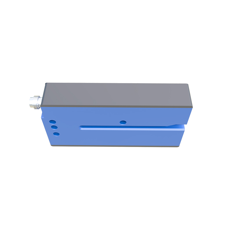
2. Setting Up the CAD Environment for Sensor Design
Open your preferred CAD software (e.g., SolidWorks, AutoCAD Electrical, or Fusion 360). Set units to millimeters for consistency with industrial standards. Create a new part file. Use reference planes to align the sensor’s optical axis. For a through-beam sensor, model the emitter and receiver as separate components. Apply material properties like ABS plastic for the housing and glass for the lens. Use the ‘Shell’ feature to hollow out the body for internal electronics. Remember to include a threaded mounting hole (e.g., M18) for easy installation.
3. Modeling the Housing and Optical Components
Begin with a base extrusion for the sensor housing. Add fillets to edges for durability. For the lens, create a circular cutout and insert a transparent cylinder. Use the ‘Revolve’ feature for dome-shaped lenses common in diffuse sensors. For retro-reflective types, model a reflector as a separate assembly. Ensure the CAD model includes an indicator LED hole (often red or green). Use ‘Pattern’ commands to replicate mounting tabs. Verify clearance with standard cable glands (e.g., PG9) by adding a cylindrical boss.
4. Incorporating Electrical Connectors and Cabling
Add a cable entry point using a boss or cutout. Model the M12 connector (4-pin or 5-pin) as a standard part library. Use ‘Loft’ to create a strain relief boot. For sensor cables, route flexible tubes in the assembly. In 2D CAD (e.g., AutoCAD), draw a schematic symbol for the sensor — typically a rectangle with a light beam icon. Annotate pin numbers (1: VCC, 2: Output, 3: GND, 4: NPN/PNP). This helps in panel layout drawings.
5. Creating an Assembly and Exploded View
Combine all components into a sensor assembly. Use ‘Mate’ constraints to align the lens with the housing. Generate an exploded view to show the internal PCB, LED, and phototransistor. This is valuable for technical documentation. Add bill of materials (BOM) with part numbers. For automated systems, export the model as STEP (.stp) or IGES (.igs) for compatibility with plant layout software. In BIM projects, use IFC format.
6. Validating the CAD Model for Practical Use
Perform interference checks to ensure no overlapping components. Simulate mounting on a conveyor rail using a DIN rail clip. Check that the sensing distance (e.g., 10m for through-beam) aligns with the optical design. In 3D CAD, render the model with realistic materials for client presentations. For electrical schematics, link the CAD model to a PLC I/O card drawing. Finally, save the file with a standardized naming convention: PHOTO_SENSOR_THROUGH_BEAM_V1.