Introduction to Reflective Photoelectric Sensing in Biomedical Applications
In the field of biomedical instrumentation, reflective photoelectric sensors have emerged as a non-invasive and cost-effective solution for monitoring physiological parameters such as pulse rate. Unlike transmissive sensors, which require direct alignment of emitter and detector, reflective sensors operate by emitting light toward the skin and detecting the intensity of backscattered light modulated by blood volume changes in tissue. This principle is rooted in photoplethysmography (PPG), where variations in light absorption due to arterial pulsation are captured to derive heart rate. For industrial and clinical engineers, understanding the optical path design, noise suppression, and signal conditioning is critical to achieving reliable measurements.
Working Principle of the Reflective Photoelectric Sensor
The reflective photoelectric sensor typically comprises an infrared or red LED as the light source and a photodiode or phototransistor as the detector. The LED emits light, which penetrates the superficial layers of the skin and is partially absorbed by blood in the microvascular bed. During systole, blood volume increases, leading to higher absorption and reduced reflected light intensity. Conversely, during diastole, reflected light intensity rises. The detector converts these optical fluctuations into a photocurrent, which is then amplified and filtered to extract the pulsatile component. Key parameters include the emitter-detector spacing, typically 4 to 10 mm, to optimize penetration depth and minimize motion artifacts.
Hardware Architecture and Component Selection
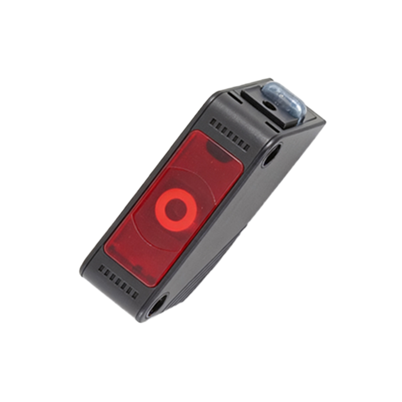
A typical pulse measurement system using a reflective photoelectric sensor consists of three main blocks: the sensor interface, analog signal conditioning, and analog-to-digital conversion (ADC). For the sensor, components such as the TCRT1000 or SFH7050 are commonly employed due to their integrated emitter-detector pair and compact surface-mount package. The analog stage includes a transimpedance amplifier to convert the photocurrent to a voltage, followed by a high-pass filter with a cutoff around 0.5 Hz to remove DC baseline drift, and a low-pass filter with a cutoff of 10 Hz to eliminate high-frequency noise. A 12-bit or higher ADC samples the conditioned signal at 100 Hz to ensure adequate temporal resolution for pulse rate extraction.
Signal Processing and Pulse Rate Calculation
Once the digitized PPG signal is acquired, digital signal processing techniques are applied to derive the pulse rate. The raw signal often contains low-frequency baseline wander and high-frequency interference from ambient light or motion. A bandpass filter with passband from 0.5 to 5 Hz is implemented using a finite impulse response (FIR) or infinite impulse response (IIR) filter. After filtering, peak detection algorithms, such as adaptive thresholding or autocorrelation, identify systolic peaks. The time interval between consecutive peaks is calculated to obtain the inter-beat interval (IBI), and the pulse rate is derived as 60/mean IBI. For enhanced accuracy, a moving average over 5 to 10 beats is used to smooth transient fluctuations.
Calibration and Environmental Considerations
To ensure consistent performance across different skin tones, perfusion levels, and ambient lighting conditions, calibration procedures are necessary. A reflective sensor output varies with skin melanin content, so a gain adjustment mechanism via a digital potentiometer or software scaling is recommended. Shielding the sensor from ambient light using an opaque enclosure or employing modulated light and synchronous detection can reduce interference. Temperature stability of the LED and photodiode should also be considered, as output drifts with temperature. For industrial applications, a calibration curve linking sensor output to known pulse rates from a reference device, such as an ECG monitor, is established to validate system accuracy.
Practical Implementation and Testing Results
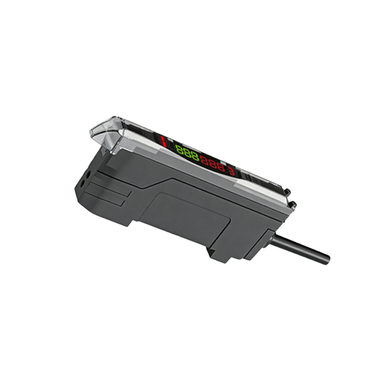
In a practical implementation on a microcontroller platform like the STM32 or Arduino Due, the reflective photoelectric sensor system was tested on 10 volunteers. The sensor was placed on the fingertip, and data were collected for 60 seconds. The calculated pulse rates ranged from 62 to 98 beats per minute, with an average absolute error of ±2 bpm compared to a commercial pulse oximeter. The signal-to-noise ratio was approximately 20 dB after digital filtering. Engineers should note that motion artifacts remain a challenge, and incorporating accelerometer-based motion cancellation could further improve robustness. The system's low power consumption, under 50 mW, makes it viable for portable health monitoring devices.