Understanding the E3Z Sensor Basics
The Omron E3Z series photoelectric sensor is a robust, compact device widely used in industrial automation for object detection. Before adjustment, verify the sensor model (e.g., through-beam, retro-reflective, or diffuse reflective) as each type requires specific setup. Ensure the power supply is stable within the rated voltage range (12-24V DC) and that the wiring matches the output type (NPN or PNP). Check the sensor's LED indicators: a steady green light typically signals power, while orange or red indicates detection status. Always clean the lens surface from dust, oil, or debris to avoid false readings. If the sensor has a sensitivity potentiometer, locate it on the rear or side panel; some models may include a time-delay adjustment screw.
Step-by-Step Sensitivity Adjustment
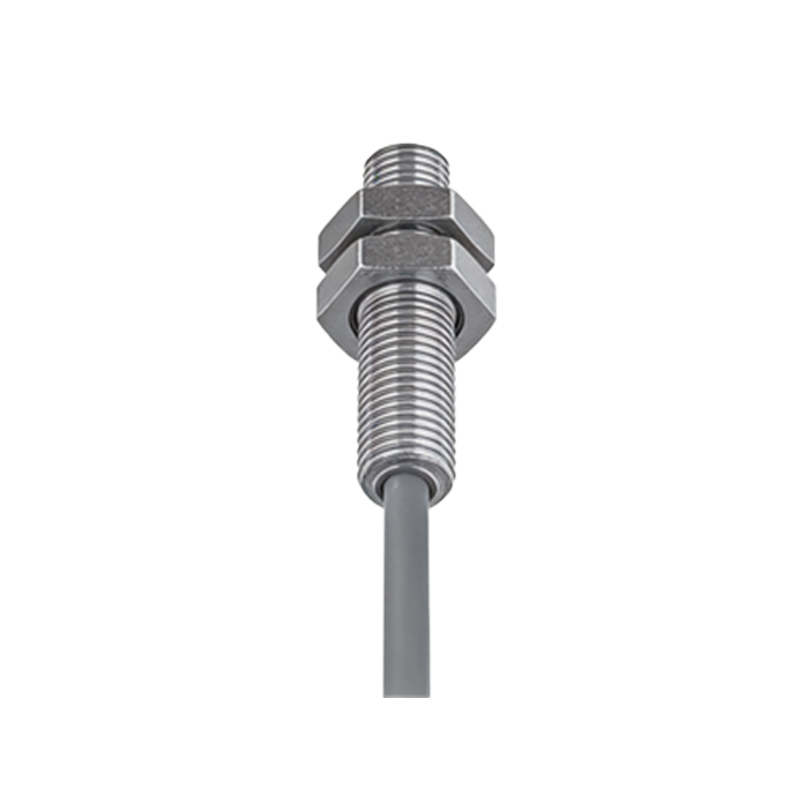
Begin by mounting the sensor at the recommended distance from the target object, as specified in the datasheet (e.g., 0.1-2 meters for retro-reflective types). For diffuse reflective sensors, the detection range depends on the target's reflectivity. Turn the sensitivity potentiometer clockwise to increase detection distance or counterclockwise to reduce it. Use a test object that matches the actual target in size, color, and material. Slowly rotate the pot while observing the output LED: it should toggle on/off precisely when the object enters or leaves the detection zone. Avoid overtightening the pot to prevent mechanical damage. For through-beam sensors, align the emitter and receiver units carefully using the alignment indicator if available. If the sensor has a teach-in function, refer to the manual for push-button tuning, which often involves holding the button until the LED flashes, then presenting the object.
Calibrating for Specific Environmental Conditions
Industrial environments with dust, vibration, or ambient light may require recalibration. For high-ambient light areas, such as near welding stations, increase the sensitivity to compensate for interference. If the sensor suffers from background suppression issues (e.g., detecting a shiny floor instead of a matte object), reduce sensitivity and test with the actual background. For sensors with a built-in timer, adjust the ON-delay or OFF-delay potentiometer to filter out brief signal fluctuations, such as from passing conveyor belt vibrations. Always perform a "worst-case" test: simulate the harshest conditions (e.g., low light, fast-moving objects) and verify stable detection. Document the final settings for future maintenance.
Troubleshooting Common Adjustment Issues
If the sensor fails to detect reliably after adjustment, first check the alignment: misalignment by even 1 degree can cause failures in through-beam models. Verify that the reflector or target is not damaged or dirty. For retro-reflective sensors, ensure the reflector is perpendicular to the sensor beam. If the output stays constantly on or off, inspect the wiring for shorts or incorrect polarity. A flickering output may indicate electrical noise; install a ferrite core on the cable or separate sensor lines from power cables. If the sensitivity pot has no effect, the sensor may be defective—compare readings with a known working unit. In rare cases, reset the sensor by cycling power or performing a factory reset via the teach button (if available).
Advanced Tips for Precision Applications
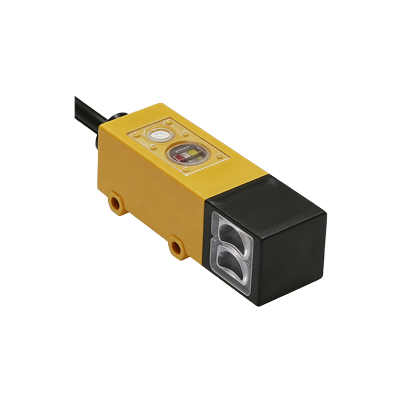
For high-speed sorting lines, set the sensor's response time to the fastest mode (e.g., 1 ms) via the DIP switch or software, but be aware that increased speed may reduce detection distance. Use a stable mounting bracket with vibration dampeners to prevent drift. For transparent object detection (e.g., glass or plastic bottles), select a retro-reflective model with a polarized filter and adjust sensitivity to the minimum stable detection level to avoid false triggers. If integrating with a PLC, confirm the output signal matches the input card specifications (e.g., sinking/sourcing). Finally, regularly recalibrate the sensor after maintenance or component replacement to maintain accuracy.