Understanding the Photoelectric Sensor’s Role in Flow Measurement
As a seasoned electrical engineer specializing in industrial automation, I emphasize that the photoelectric sensor is a critical component in modern flow meters, particularly in turbine and paddlewheel designs. These sensors detect the rotation of blades or the passage of fluid particles via a light beam, converting optical signals into electrical pulses for flow rate calculation. Proper wiring is non-negotiable for signal integrity and reliable performance. In my field experience, even minor wiring errors—such as reversed polarity or improper shielding—can lead to erratic readings or complete sensor failure. Always begin by consulting the manufacturer’s datasheet for your specific sensor model, as pin configurations vary between brands like Honeywell, Omron, or Keyence. Common wiring types include 3-wire PNP (source) or NPN (sink) configurations, and 2-wire DC systems. For this guide, I assume a standard 3-wire PNP configuration, which is prevalent in flow meters for its noise immunity.
Essential Tools and Safety Precautions Before Wiring
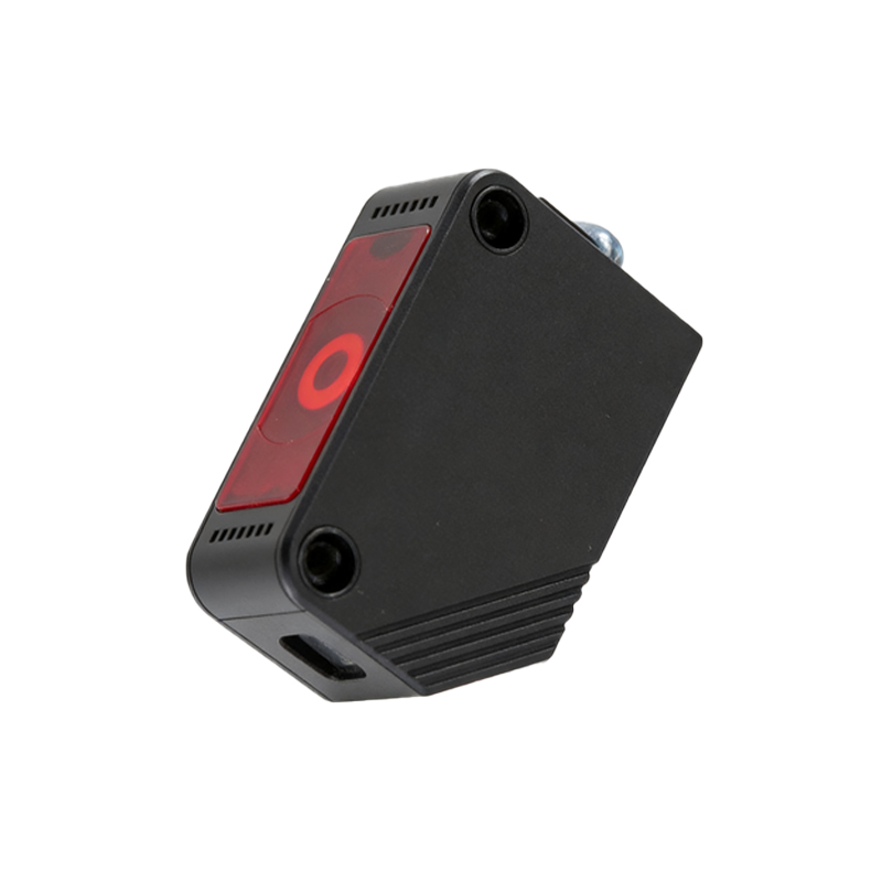
Before handling any wiring, safety must be paramount. I recommend using a digital multimeter (DMM) with resistance and voltage measurement capabilities, a set of precision screwdrivers, wire strippers (20-26 AWG), and heat-shrink tubing for insulation. Shut down the entire system and disconnect power from the flow meter’s controller or PLC (Programmable Logic Controller). Verify with your DMM that no residual voltage exists on the power lines. For hazardous environments (e.g., explosive gas areas), ensure compliance with ATEX or NEC Class I, Division 1 standards by using intrinsically safe barriers. Wear anti-static wrist straps to protect the sensor’s sensitive electronics from electrostatic discharge (ESD). In my practice, I always tag the wires with labels (e.g., “+24V,” “GND,” “Signal”) to avoid confusion during troubleshooting.
Step-by-Step Wiring Procedure for a 3-Wire PNP Photoelectric Sensor
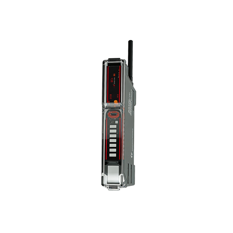
The typical 3-wire PNP sensor has three leads: brown (positive power supply, +24 VDC), blue (negative power supply, 0 VDC or GND), and black (output signal). Connect the brown wire to the 24 VDC terminal of your flow meter’s control unit or power supply. Secure it tightly with a screw terminal or a soldered joint if using a junction box. The blue wire goes to the common ground (0V). For the black output wire, connect it to the digital input of your PLC or flow meter controller. In a PNP configuration, the output is “high” (sourcing current) when the sensor detects a target—for example, a rotating blade. If using an NPN sensor, the black wire would sink to ground when triggered. After connections, use your DMM to check for shorts: measure resistance between brown and blue (should be high, >1 MΩ); then between black and blue (should also be high). Apply power and verify the sensor’s supply voltage at brown to blue (should be 24 VDC ±10%). Use a piece of dark paper or a reflective object to simulate the target, and check the black wire’s voltage: it should toggle between 0V (no target) and 24V (target present). If not, recheck polarity and wiring.
Common Wiring Errors and Troubleshooting Tips
From my repair logs, the most frequent mistake is swapping the blue and black wires, which causes the sensor to not trigger or output a constant high signal. Another issue is using an incorrect power voltage—some photoelectric sensors require 10-30 VDC, but applying 24 VDC to a 5V-rated model can damage it instantly. If you encounter intermittent signals, suspect poor grounding or electromagnetic interference (EMI). Use shielded twisted-pair cables for the signal line, with the shield connected to ground at one end only to avoid ground loops. For long cable runs (over 50 meters), install a surge suppressor or filter to protect against voltage spikes. In one project, I resolved a persistent noise issue by adding a 0.1 µF ceramic capacitor across the power terminals (brown to blue) at the sensor. Always document your wiring changes and test the flow meter’s output with a frequency counter or oscilloscope to ensure clean pulses.
Final Verification and Integration into the Flow Meter System
After wiring, perform a live test. Connect the flow meter to the piping system, initiate fluid flow, and monitor the sensor’s pulse frequency on a PLC display or handheld tachometer. The output should be a square wave with a 50% duty cycle at nominal flow rates. If the signal is too weak, adjust the sensor’s sensitivity potentiometer (if available) or check for optical obstructions on the lens. Seal all connections with heat-shrink tubing or silicone gel to prevent moisture ingress, which is a leading cause of sensor failure in outdoor or washdown environments. Finally, update your system’s wiring diagram to reflect the exact connections, including wire colors and terminal numbers. This documentation saves hours during future maintenance. Remember, a well-wired photoelectric sensor ensures accurate flow measurement and extends equipment lifespan.