Introduction to Photoelectric Sensor Markings
Photoelectric sensors are critical components in industrial automation, relying on optical principles to detect objects without physical contact. As an electrical engineer, interpreting the markings on these sensors is essential for correct installation, troubleshooting, and integration into control systems. These markings, typically found on the sensor housing or datasheet, provide key parameters such as sensing range, output type, power supply voltage, and environmental ratings. This article decodes common symbols and alphanumeric codes to enhance your practical understanding.
Power Supply and Voltage Ratings
Look for markings like "10-30 VDC" or "24 VDC" indicating the operating voltage range. For AC sensors, markings such as "24-240 VAC" are common. These values specify the electrical input required for the sensor to function. Pay attention to polarity symbols: "+" for positive, "-" for negative, and a ground symbol (⏚) for earth connection. Some sensors feature universal power supplies, denoted by "PWR" or "U" on the label, accepting both AC and DC.
Output Type and Configuration
Output markings define how the sensor interfaces with a controller. Common codes include "NPN" (sinking output) and "PNP" (sourcing output), often paired with "NO" (normally open) or "NC" (normally closed). For example, "PNP NO" means the output switches to a high state when an object is detected. Additionally, analog outputs may be labeled "4-20 mA" or "0-10 V". Look for symbols like a transistor icon or a relay coil for solid-state or electromechanical outputs.
Detection Principle and Sensing Range
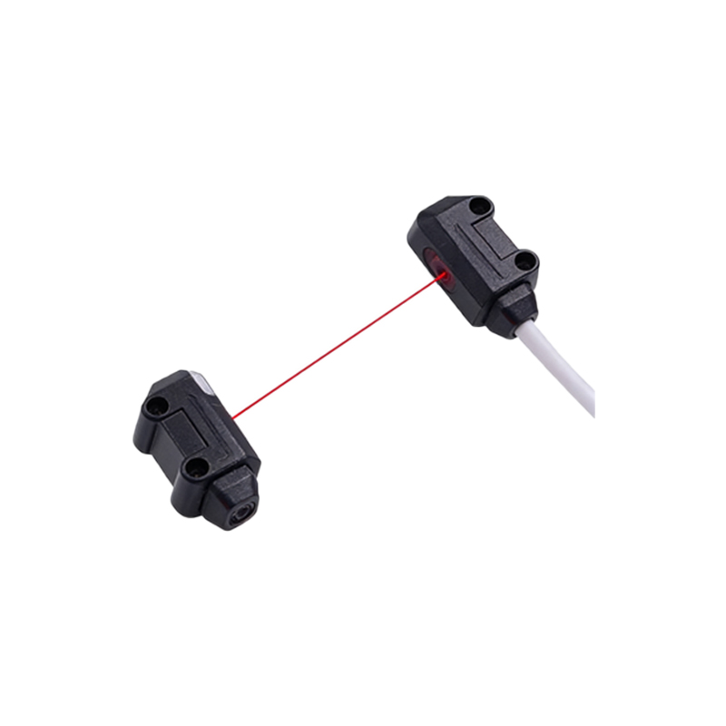
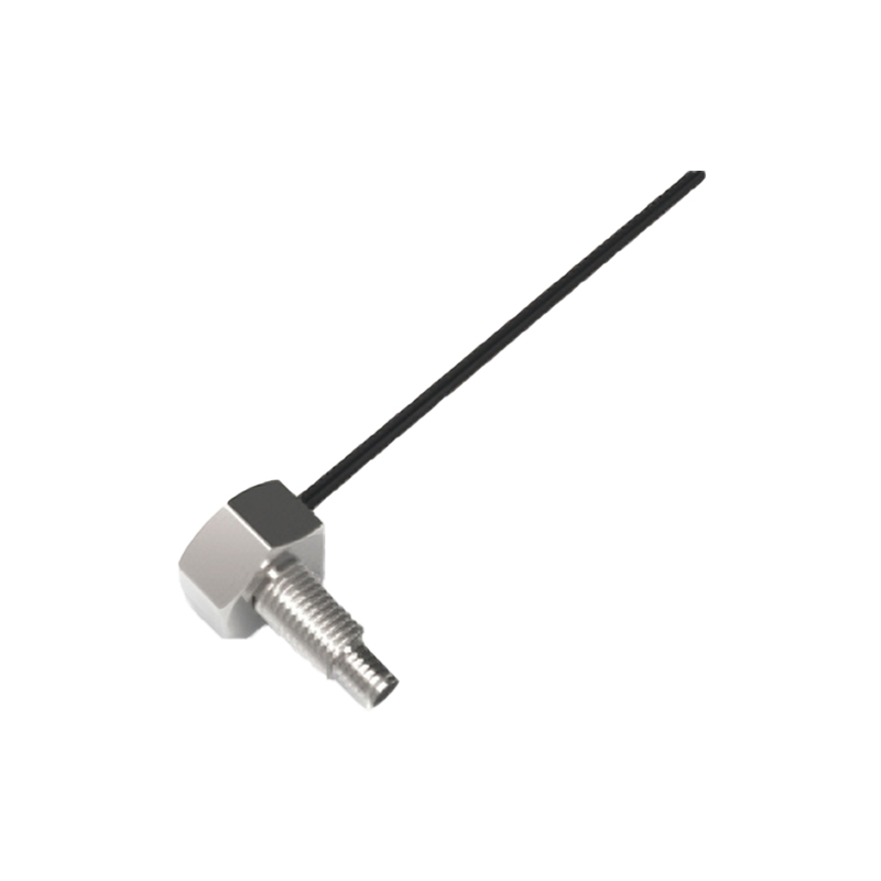
Markings indicating the sensing technology are crucial: "Through-beam" (or "T"), "Retro-reflective" (or "R"), and "Diffuse" (or "D") are standard. The sensing range is often printed as a distance, e.g., "10 m" for through-beam or "0.5 m" for diffuse. Some sensors include a beam pattern symbol, such as a cone or line, to show the detection area. For fiber optic versions, you might see "FO" with a fiber cable length specification.
Environmental and Protection Ratings
Environmental markings ensure the sensor withstands industrial conditions. IP ratings like "IP67" indicate dust and water resistance. Temperature ranges are shown as " -20°C to +60°C". For harsh environments, look for "NEMA 4X" or "UL" certification. Additionally, symbols for ambient light rejection (e.g., a sun icon) or vibration resistance may appear. Check for "CE" or "FCC" marks for compliance.
Connection and Wiring Diagrams
A wiring diagram is often printed on the sensor or included in the manual. Common connection markings include "BN" (brown for V+), "BU" (blue for V-), "BK" (black for output), and "WH" (white for auxiliary or test input). For M12 connectors, pin numbers (1-4) are labeled. A typical 4-wire sensor might show: Pin 1 (brown) = 24V, Pin 2 (white) = NC, Pin 3 (blue) = 0V, Pin 4 (black) = output. Always verify polarity with a multimeter before powering up.
Diagnostic and Adjustment Markings
Many sensors feature indicators like green LED for power, yellow LED for output status, and red LED for error or alignment. Adjusting potentiometers may be labeled "Sensitivity" or "Range" with a small arrow symbol. Some advanced sensors have a "Teach" button marked with a "T" or a gear icon for setting thresholds. Look for a "Lock" symbol to prevent accidental parameter changes.