Understanding the Two-Wire Photoelectric Sensor
Two-wire photoelectric sensors are widely used in industrial automation for object detection without physical contact. Unlike three- or four-wire sensors, these devices use only two conductors for both power supply and signal output. This design simplifies installation and reduces wiring costs, making them ideal for space-constrained or cost-sensitive applications. The sensor operates by emitting a light beam (infrared or visible) and detecting changes in the received light. When an object interrupts or reflects the beam, the sensor switches its output state, which is typically a normally open (NO) or normally closed (NC) configuration.
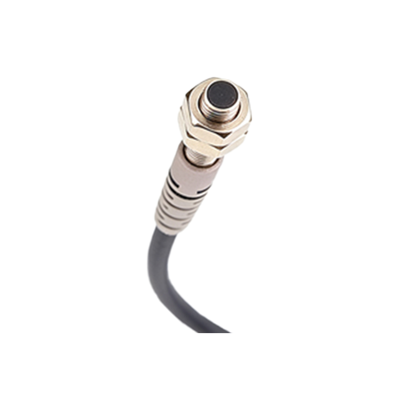
Key Components of the Wiring Diagram
A typical two-wire photoelectric sensor wiring diagram includes two primary terminals: a brown wire (positive supply, usually 10-30 VDC) and a blue wire (negative supply or ground). In some models, the brown wire serves as the power input, while the blue wire acts as both ground and signal output. The sensor acts as a switch in series with the load, such as a relay coil, PLC input, or indicator light. It is crucial to note that the load must be connected between the sensor and the power supply to ensure proper operation. The sensor draws a small leakage current even in the off state, so the load must be compatible with this current to avoid false triggering.
Step-by-Step Wiring Procedure
1. Identify the sensor wires: Brown (V+), Blue (0V/GND), and sometimes a third wire for shield or diagnostic, but in two-wire models, these are absent.
2. Connect the brown wire to the positive terminal of the DC power supply (e.g., 24 VDC).
3. Connect the blue wire to one side of the load (e.g., a relay coil or PLC input).
4. Connect the other side of the load to the negative terminal of the power supply (0V).
5. Ensure the load is rated for the sensor’s voltage and current range. For example, if the sensor outputs 100 mA, the load must not exceed this limit.
6. Verify polarity: Reversing the wires can damage the sensor or cause malfunction. Always use a multimeter to check continuity before powering up.
Common Applications and Load Types
Two-wire photoelectric sensors are often used in conveyor systems, packaging machines, and material handling equipment. The load can be a DC relay coil, a PLC digital input module, or a small solenoid valve. For inductive loads like relays, a flyback diode should be installed across the coil to protect the sensor from voltage spikes. In some cases, the sensor can directly drive a logic input, but the leakage current of the sensor (typically 1-3 mA) must be within the input’s threshold to avoid false ON states. Always check the sensor datasheet for specific leakage and load compatibility.
Wiring Diagram Example
Consider a 24 VDC system with a two-wire sensor and a relay. Connect the brown wire to the 24V terminal of the power supply. Connect the blue wire to one terminal of the relay coil. Connect the other terminal of the relay coil to the 0V terminal of the power supply. When an object is detected, the sensor completes the circuit, energizing the relay. This simple configuration ensures reliable operation in most industrial environments. For PLC connections, replace the relay with the PLC input module (sink or source type, depending on polarity). Always follow the manufacturer’s schematic to avoid wiring errors.
Troubleshooting Common Issues
If the sensor fails to operate, check the power supply voltage and polarity first. A common problem is insufficient load current: if the load draws less than the sensor’s minimum load current (e.g., 5 mA), the sensor may not switch reliably. Another issue is excessive leakage current, which can cause the load to remain partially energized. Use a multimeter to measure voltage across the sensor output in both states. Ensure the wiring environment is free of electromagnetic interference (EMI) from motor drives or high-frequency devices. Finally, inspect the sensor lens for dust or debris that might block the light beam.