Introduction to Photoelectric Sensors and PLC Integration
Photoelectric sensors are essential components in modern industrial automation, detecting objects, distances, and positions using light beams. When integrated with Programmable Logic Controllers (PLCs), these sensors enable precise control in manufacturing lines, packaging systems, and material handling. Proper wiring and understanding of terminal diagrams are critical to ensure reliable operation and minimize downtime. This guide provides a step-by-step approach to connecting photoelectric sensors to PLCs, focusing on standard wiring practices and troubleshooting.
Understanding Photoelectric Sensor Types and Outputs
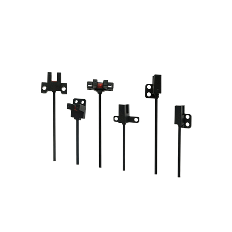
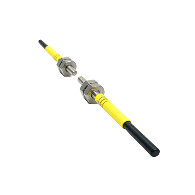
Photoelectric sensors come in three main types: through-beam, retro-reflective, and diffuse. Each type has distinct wiring requirements. Through-beam sensors use a separate emitter and receiver, requiring two pairs of wires for power and signal. Retro-reflective sensors combine emitter and receiver in one unit, using a reflector, while diffuse sensors detect reflected light from the target. Outputs are typically NPN (sinking) or PNP (sourcing). Choose the correct output type based on your PLC input module: NPN for sinking inputs (common negative) and PNP for sourcing inputs (common positive). For example, a PNP sensor connects its output to the PLC input pin, with the load connected to the positive supply.
PLCs and Input Module Wiring Basics
PLC input modules have specific terminal configurations. A typical 8-point DC input module includes terminals for common (COM), input channels (I0.0 to I0.7), and power supply (DC 24V). For NPN sensors, connect the sensor’s output (usually brown wire) to the PLC input, and the sensor’s common (blue wire) to the PLC COM terminal. For PNP sensors, connect the output (black wire) to the PLC input, and the sensor’s power (brown) to the PLC 24V, with COM connected to 0V. Always verify the sensor’s datasheet for wire color codes and voltage ranges (typically 10-30VDC). Use shielded cables for long runs to prevent electromagnetic interference.
Step-by-Step Wiring Diagram Example
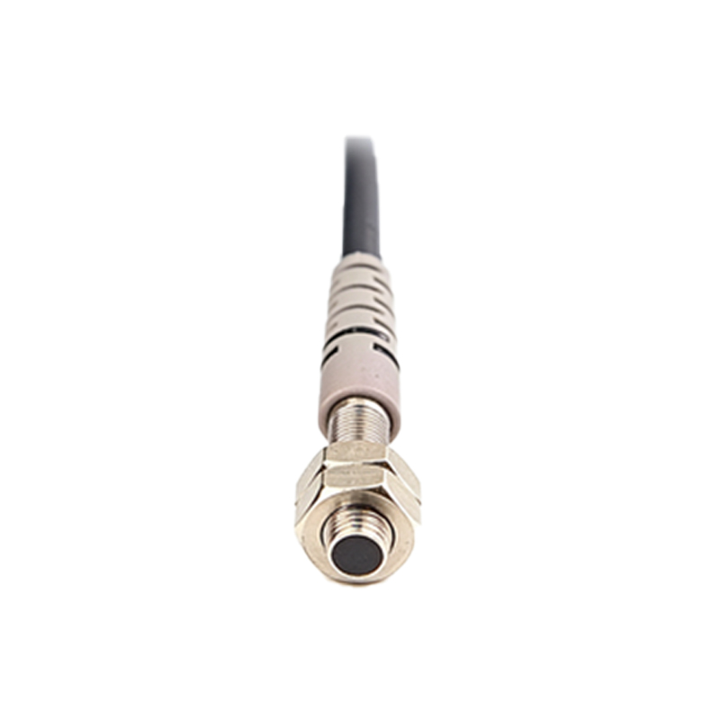
Consider a retro-reflective PNP sensor wired to a Siemens S7-1200 PLC. The terminal diagram: Sensor brown wire to PLC terminal L+ (24VDC); blue wire to PLC terminal M (0VDC); black wire to PLC input I0.0. The PLC common terminal (2M) must be connected to 0VDC. For NPN configuration, use a pull-up resistor (e.g., 10kΩ) between the sensor output and 24VDC if the PLC input lacks internal pull-up. The wiring sequence: (1) Disconnect power. (2) Connect sensor power wires to appropriate terminals. (3) Connect signal wire to input. (4) Verify polarity with a multimeter. (5) Power up and test by obstructing the sensor beam.
Common Wiring Mistakes and Troubleshooting Tips
Frequent issues include reversed polarity (e.g., swapping brown and blue wires), which can damage the sensor. Always use a fuse on the power line (e.g., 0.5A for sensors). If the PLC input remains high when the sensor is blocked, check for false triggering due to reflections or ambient light. Use a multimeter to measure voltage at the input terminal: it should toggle between 0V and 24V. Loose connections in a terminal block cause intermittent faults; tighten screws to 0.5 Nm. For long cables, use twisted-pair shielded wires with the shield grounded at one end to reduce noise.
Advanced Integration: Using PLC Programming with Sensor Feedback
After wiring, configure the PLC software. For example, in TIA Portal, assign the input address (e.g., %I0.0) to a sensor. Write a simple ladder logic: a normally open contact for the sensor input activates a timer or counter. For high-speed applications (e.g., counting items on a conveyor), use high-speed counter modules or fast input terminals with filter time set to 0.1 ms. Integrate sensor feedback with actuators: if the sensor detects an object, trigger a solenoid valve or motor. Always add a delay (e.g., 50 ms) to debounce sensor signals.
Safety and Best Practices for Industrial Environments
Ensure all wiring complies with IEC 61131-2 standards. Use ferrules on stranded wires to prevent fraying. Label all cables with heat-shrink markers for easy identification. Install surge protection devices on power lines. For harsh environments (dust, moisture), use IP67-rated connectors and enclosures. Regularly inspect terminals for corrosion or loosening. Document the wiring diagram in a maintenance manual. Perform a functional test after installation: simulate object detection and verify the PLC input status via software monitoring.
Conclusion: Optimizing Sensor-to-PLC Connections
Mastering photoelectric sensor wiring to PLCs enhances system reliability and reduces troubleshooting time. By understanding sensor types, PLC input modules, and correct terminal connections, engineers can design robust automation systems. Always refer to the manufacturer’s datasheet for specific wiring details. With practice, these guidelines become second nature, ensuring efficient industrial operations.