Introduction to Photoelectric Sensors in Industrial Automation
Photoelectric sensors are essential components in modern industrial automation systems, used for detecting the presence, absence, or distance of objects without physical contact. These sensors emit a beam of light and measure the reflection or interruption to trigger outputs. Proper disassembly and installation are critical for maintaining system reliability and safety. This guide provides detailed methods and diagrams for both tasks, tailored for electrical engineers and technicians. Always refer to the manufacturer’s manual for specific models, as variations in design may affect procedures.
Safety Precautions Before Disassembly or Installation
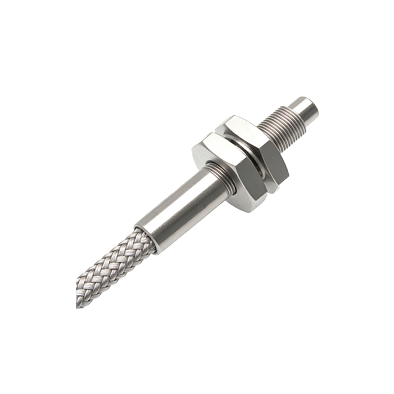
Before handling any photoelectric sensor, ensure the power supply is completely disconnected. Use a lockout-tagout (LOTO) procedure to prevent accidental re-energization. Wear appropriate personal protective equipment (PPE), such as insulated gloves and safety glasses, especially when working in high-voltage or dusty environments. Ground yourself to avoid electrostatic discharge (ESD) damage to sensitive electronic components. For sensors in hazardous areas, verify compliance with ATEX or NEC standards. Always inspect cables and connectors for wear or damage before proceeding.
Required Tools and Materials for the Process
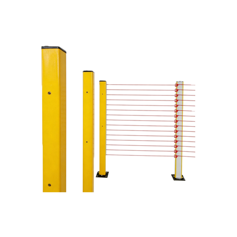
To perform disassembly and installation effectively, gather the following tools: a set of precision screwdrivers (flathead and Phillips), a torque wrench for tight fasteners, a multimeter for continuity checks, a cable stripper, heat shrink tubing, a soldering iron (if re-terminations are needed), and a clean, anti-static work mat. Diagrams should be prepared with clear labels for component identification. For installation, have mounting brackets, screws, and sealants (if outdoor use) ready. Ensure all tools are calibrated and in good condition.
Step-by-Step Disassembly of a Photoelectric Sensor
1. Power Down and Isolate: Confirm power is off and lock the circuit breaker. Use a multimeter to verify zero voltage at the sensor terminals.
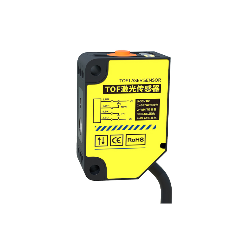
2. Remove the Housing: Locate the retaining screws or clips on the sensor housing. Use a screwdriver to loosen them carefully. For sealed units, use a gasket tool to avoid damaging the rubber seal.
3. Disconnect Internal Connections: Gently pull apart the connector pins or unsolder wires if hard-wired. Refer to the wiring diagram from the manual to avoid polarity mistakes.
4. Extract the Sensing Module: Slide out the optical lens and circuit board assembly. Place them on an anti-static mat. Clean any dust with a lint-free cloth.
5. Inspect Components: Check for corrosion, broken wires, or damaged lenses. Replace any faulty parts before reassembly. Document the disassembly order with photos for easy reassembly.
Detailed Installation Procedure with Diagrams
1. Mounting Preparation: Use the provided diagram to mark drilling points on the mounting surface. Ensure alignment with the target object’s reflective path. For through-beam sensors, align emitter and receiver directly.
2. Secure the Sensor: Attach the bracket with M4 or M5 screws, tightening to the specified torque (usually 0.5-1.0 Nm). Use a level to confirm perpendicularity.
3. Wiring Connections: Strip cable ends to 5 mm. Connect according to the color code: brown (positive), blue (negative), black (output). For PNP sensors, output is active high; for NPN, active low. Solder or use terminal blocks. Apply heat shrink for insulation.
4. Optical Alignment: Power up temporarily. Use a paper target to verify beam interruption. Adjust the sensor angle by loosening the bracket screws and realigning. Tighten fully once the indicator LED shows stable detection.
5. Final Testing: Re-test with actual objects at the required distance. Confirm response time meets specifications. Seal cable entries with conduit fittings to prevent moisture ingress.
Common Troubleshooting Tips and Best Practices
If the sensor fails after installation, check power supply voltage first (typically 10-30 VDC). Examine the lens for dirt or scratches, which can cause false readings. For disassembly, avoid excessive force on plastic housings, as they may crack. Use dielectric grease on connectors in wet environments. Always keep a spare sensor for critical systems. Document all steps in a maintenance log for future reference. For complex installations, consider using a laser alignment tool for precise optical paths.
Conclusion and Safety Reminder
Mastering photoelectric sensor disassembly and installation enhances system uptime and safety in industrial applications. Always follow the manufacturer’s guidelines and update your knowledge with new sensor technologies. After completing the task, clean the work area and restore power gradually, monitoring for any anomalies. For advanced troubleshooting, consult with the engineering team or the supplier’s technical support.