Introduction to Photoelectric Sensor Icons
Photoelectric sensors are critical components in industrial automation, and their icons provide essential operational information at a glance. These standardized symbols, often found on sensor housings or in datasheets, indicate key features such as sensing mode, output type, and environmental ratings. As an electrical engineer, interpreting these icons correctly ensures proper installation, troubleshooting, and system reliability. This article decodes common photoelectric sensor icons, aiding professionals in optimizing system performance.
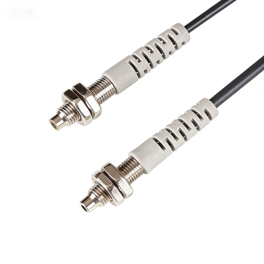
Sensing Mode Indicators
The most prominent icons on photoelectric sensors denote the sensing mode. For instance, a circle with an arrow pointing outward represents a through-beam sensor, where the emitter and receiver are separate. A rectangle with a curved arrow indicates a diffuse reflective sensor, which detects objects by reflecting light off the target. A square with a diagonal line or a double arrow signifies a retro-reflective sensor, using a reflector to bounce the beam. Understanding these icons is crucial for selecting the correct sensor for a given application, whether for long-range detection or in challenging environments with dust or mist.
Output and Wiring Icons
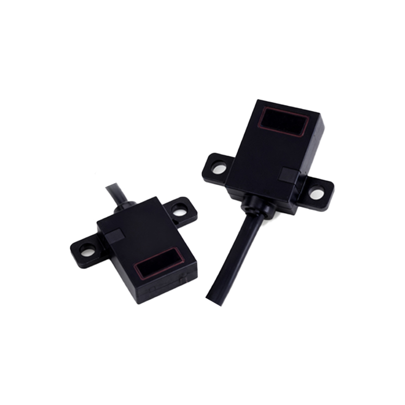
Output configurations are typically shown with electrical symbols. A common icon is a circle with a plus sign (+), indicating a PNP (sourcing) output, while a circle with a minus sign (-) denotes an NPN (sinking) output. A lightning bolt icon may represent a normally open (NO) or normally closed (NC) state, often accompanied by letters like "NO" or "NC." Additionally, a four-pin or three-pin connector icon, such as a small rectangle with dots, indicates the wiring schematic, helping engineers connect the sensor to a PLC or controller correctly. Misinterpreting these can lead to system faults, so careful attention is required.
Environmental and Protection Icons
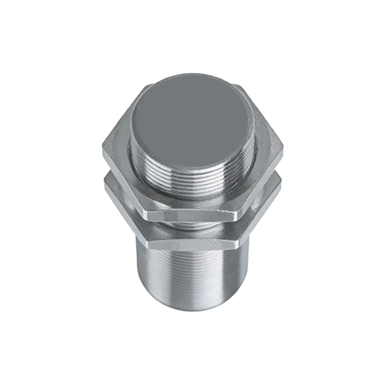
Environmental resistance is vital for industrial sensors. The IP (Ingress Protection) rating is often shown as a two-digit number, like "IP67," where "6" indicates complete dust protection and "7" signifies water immersion resistance. A snowflake icon may denote a cold-resistant model, while a sun icon indicates high-temperature or UV resistance. A shield with a lightning bolt suggests surge or overvoltage protection. These icons guide sensor selection for harsh conditions, such as in food processing plants or outdoor conveyor systems.
Adjustment and Calibration Icons
Many photoelectric sensors feature potentiometers for sensitivity or timing adjustments. A rotating arrow icon or a screwdriver symbol points to the adjustment location. A circle with a "T" inside might indicate a time delay setting, while a "G" could represent gain or sensitivity. An LED indicator, often a small light bulb icon, shows the sensor's output state during calibration. Engineers should familiarize themselves with these icons to fine-tune sensor performance, reducing false triggers or missed detections.
Communication and Advanced Features
Modern smart sensors integrate communication protocols. An icon with a coiled cable and a plug represents an IO-Link interface, enabling bidirectional data exchange. A Wi-Fi symbol or Bluetooth "B" indicates wireless connectivity for remote monitoring. A gear icon may denote programmable parameters, while a bar graph icon shows signal strength or distance measurement. These icons are increasingly common in Industry 4.0 applications, requiring engineers to stay updated on digital sensor capabilities.
Safety and Compliance Marks
Safety certifications are displayed as icons like a CE mark (two overlapping C's) for European compliance, a UL listing (a circle with "UL"), or a RoHS symbol (a checkmark with "RoHS") indicating lead-free materials. A triangle with an exclamation mark warns of electrostatic discharge (ESD) sensitivity. For safety-rated sensors, a yellow triangle with an "S" may denote safety level, such as SIL (Safety Integrity Level) or PL (Performance Level). These icons ensure the sensor meets regulatory standards for safe operation.
Conclusion: Best Practices for Icon Interpretation
Mastering photoelectric sensor icons enhances installation accuracy and reduces downtime. Always refer to the manufacturer's datasheet for specific icon definitions, as variations exist across brands. When in doubt, use a multimeter or test the sensor in a controlled setup to verify output behavior. As automation evolves, icons will likely incorporate more digital features, but the core symbols—mode, output, environment—remain foundational. By understanding these visual cues, engineers can streamline system design and maintenance.