Understanding the Alignment Principle of Omron Photoelectric Sensors
Proper alignment of an Omron photoelectric sensor is critical for ensuring consistent and accurate detection in industrial automation. The fundamental principle involves positioning the emitter and receiver (or reflector) so that the light beam is fully and squarely received. For through-beam sensors, the emitter and receiver must be directly opposite each other with no obstructions. For retro-reflective sensors, the reflector must be aligned to bounce the beam back to the receiver. For diffuse sensors, the target must reflect enough light back. Misalignment can cause false triggers, missed detections, or constant errors. Always consult the specific Omron sensor datasheet for beam angle and effective distance.
Preparing the Mounting Hardware and Environment
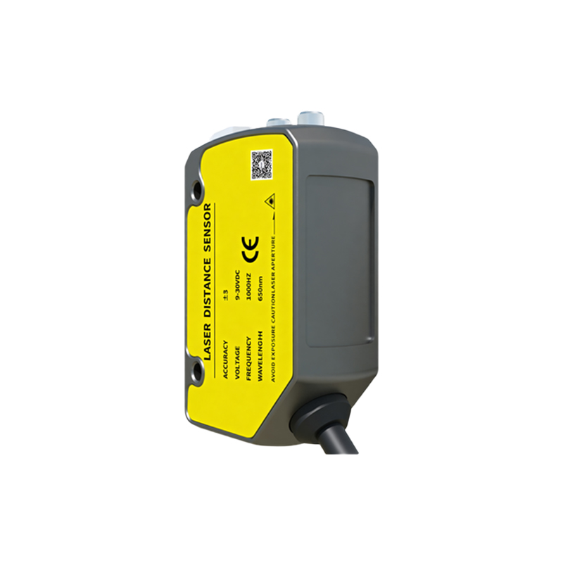
Before starting alignment, ensure the mounting brackets are securely fastened and that the sensor and reflector (if used) are clean. Use a lint-free cloth with isopropyl alcohol to remove dust, oil, or condensation from the lens and reflector surfaces. Check that the mounting surface is level and free from vibration. Use adjustable brackets if possible, as they allow fine-tuning. If the sensor is in a harsh environment, consider protective housings. Also, verify that the ambient light (e.g., from welding arcs or sunlight) does not interfere; use a sensor with a modulated light source if needed.
Step-by-Step Coarse Alignment Procedure
Start with coarse alignment to get the beam roughly on target. For through-beam sensors, position the emitter and receiver roughly facing each other. Power on the sensor and observe the indicator LED. Many Omron models have a green LED for stable detection and a yellow LED for marginal alignment. Manually adjust the emitter and receiver positions until the green LED lights up. For retro-reflective sensors, aim the sensor at the reflector while keeping the reflector centered in the sensor's field of view. Move the sensor or reflector until the LED indicates a stable received signal. For diffuse sensors, simply place a standard target at the required distance and adjust the sensor angle until the LED responds.
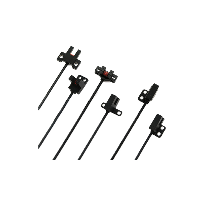
Fine-Tuning with the Alignment Indicator or Teach Function
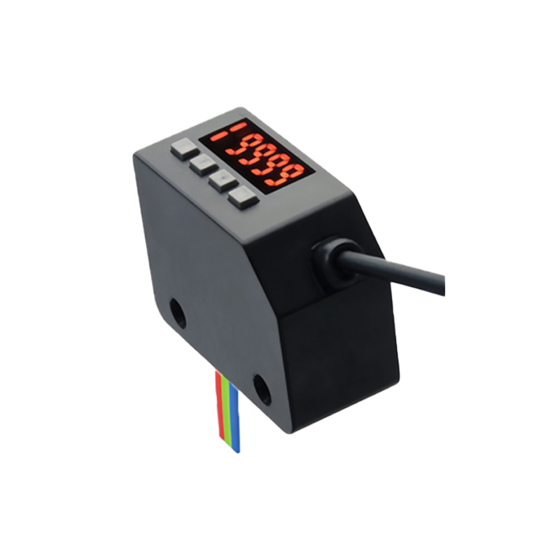
Once coarse alignment is achieved, engage the sensor's fine-tuning features. Most Omron photoelectric sensors have a "Teach" or "Fine-Adjust" mode. Press and hold the teach button for a few seconds to enter alignment tuning mode. The sensor will then emit a series of pulsed beams and analyze the received signal strength. Use the adjustment screw or digital input to move the sensor in small increments (e.g., 1-2 degrees or millimeters). Watch the signal strength indicator; some models have a bar graph on the sensor body or an external display. Aim for the highest possible signal strength, typically above 80% of the maximum. For through-beam sensors, this means the beam is perfectly coaxial with the receiver lens. For retro-reflective, it means the beam hits the reflector center.
Verifying Detection Stability and Margin
After fine-tuning, verify that the sensor has sufficient detection margin. A good margin means the sensor can still detect the target even if minor misalignment occurs (e.g., from thermal expansion or slight vibration). Use a multimeter to measure the output signal or observe the LED. The sensor should show a stable green light when the target is present and a red or no light when absent. Perform a "worst-case" test: move the target to the edges of the detection zone and check for false triggers. If the sensor uses a potentiometer, adjust the sensitivity to maximize the difference between detection and non-detection states. For digital outputs, this step is critical to prevent noise-induced errors.
Common Mistakes and Troubleshooting Tips
Avoid common pitfalls such as using too much tightening force on brackets, which can warp the sensor housing. Verify that the reflector is not scratched or faded; replace it if the signal strength is low. If using a polarizing filter (for retro-reflective on shiny objects), ensure the filter is oriented correctly. Check the cable connections for damage or moisture. If the sensor fails to align, test it with a known good reflector or target to rule out sensor failure. For Omron E3Z or E3JK series, use the built-in diagnostic LED to identify issues: continuous blinking indicates alignment problems, while a steady on/off indicates normal operation. If all else fails, reset the sensor to factory defaults and repeat the alignment procedure.